


2 Troubleshooting Procedures 2.14 Sound Troubleshooting
2-46 PORTEGE A200 Maintenance Manual (960-499)
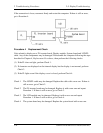
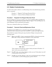
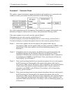
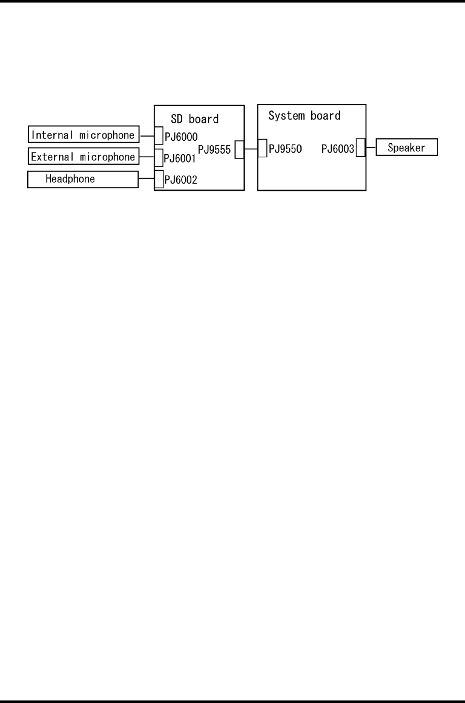
Procedure 2 Connector Check
The speaker, external microphone, internal microphone and headphone are connected to the
connectors on the system board and SD board shown in the following figure.
Any of the connections may be disconnected. Disassemble the computer following the steps
described in Chapter 4, Replacement Procedures and perform the following checks:
If the stereo speakers do not work correctly, perform Check 1.
If headphones do not work correctly, perform Check 2.
If sound recording by an external microphone does not work correctly, perform Check 3.
If sound recording by an internal microphone does not work correctly, perform Check 4.
Check 1 If the stereo speakers do not work properly, the speaker cables may be
disconnected. Make sure the speaker cables are firmly connected to PJ6003 on the
system board. If the stereo speakers are still not functioning properly, go to
Procedure 3.
Check 2 If headphones do not work properly, the SD board may be disconnected or the
headphone cable may be disconnected. Make sure the SD board is firmly
connected to PJ9550 on the system board and the headphone cable is connected to
the headphone jack PJ6002 on the SD board. If the sound function still does not
work properly, go to Procedure 3.
Check 3 If the sound recording function by an external microphone does not work properly,
the SD board may be disconnected or the external microphone cable may be
disconnected. Make sure the SD board is firmly connected to the connector PJ9550
on the system board and the external microphone cable is firmly connected to
microphone jack PJ6001 on the SD board. If recording is still not functioning
properly, go to Procedure 3.
Check 4 If the sound recording function by the internal microphone does not work properly,
the SD board may be disconnected or the internal microphone cable may be
disconnected. Make sure the SD board is firmly connected to the connector PJ9550
on the system board and the internal microphone cable is firmly connected to the
connector PJ6000 on the SD board. If recording is still not functioning properly, go
to Procedure 3.