


- 11 -
(14) Input/Output Signals
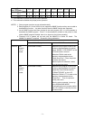
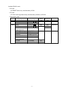
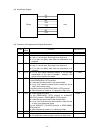
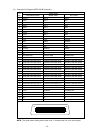
(15) Connector Pin Assignment and Signal Description
Pin No.
Signal
Name
Function Signal Direction
1 FG z Ground line for circuit protection
2 RD z Line for data which the printer receives from the host.
z Logic 1 is a Low level, while logic 0 is a High level.
z It is in the Low (Mark) state when no transmission is in
progress.
← Host
3 TD z Line for data which the printer sends to the host.
z Logic 1 is a Low level, while logic 0 is a High level.
z It is in the Low (Mark) state when no transmission is in
progress.
Printer →
4 CTS z It is an input signal indicating whether or not the data
transmission to the host is possible. However, this
printer does not detect this signal.
← Host
5 RTS z Output signal to the host.
For the READY/BUSY (RTS) protocol:
z It indicates the ready state for the received data.
z It is at “Low” when the receive buffer is nearly full, and at
“High” when nearly empty.
For protocol other than the READY/BUSY (RTS) protocol:
z After the power is turned on, it is always at “High” level.
Printer →
6 DTR z Output signal to the host.
For the READY/BUSY (DTR) protocol or XON/XOFF
(DC1/DC3) protocol + READY/BUSY (DTR) protocol:
z It indicates the ready state for the received data.
z It is at “Low” level when the receive buffer is near full, and
at “High” level when near empty.
For the XON/XOFF (DC1/DC3) protocol or READY/BUSY
(RTS) protocol:
z After the power is turned on, it is always at “High”.
Printer →
7 SG z Ground line for all data and control signals.
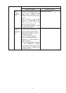
20 DSR z Input signal from the host.
z For the printer to receive data, it must be at “High” level.
← Host
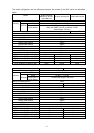
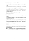
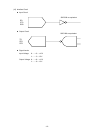
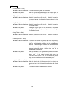
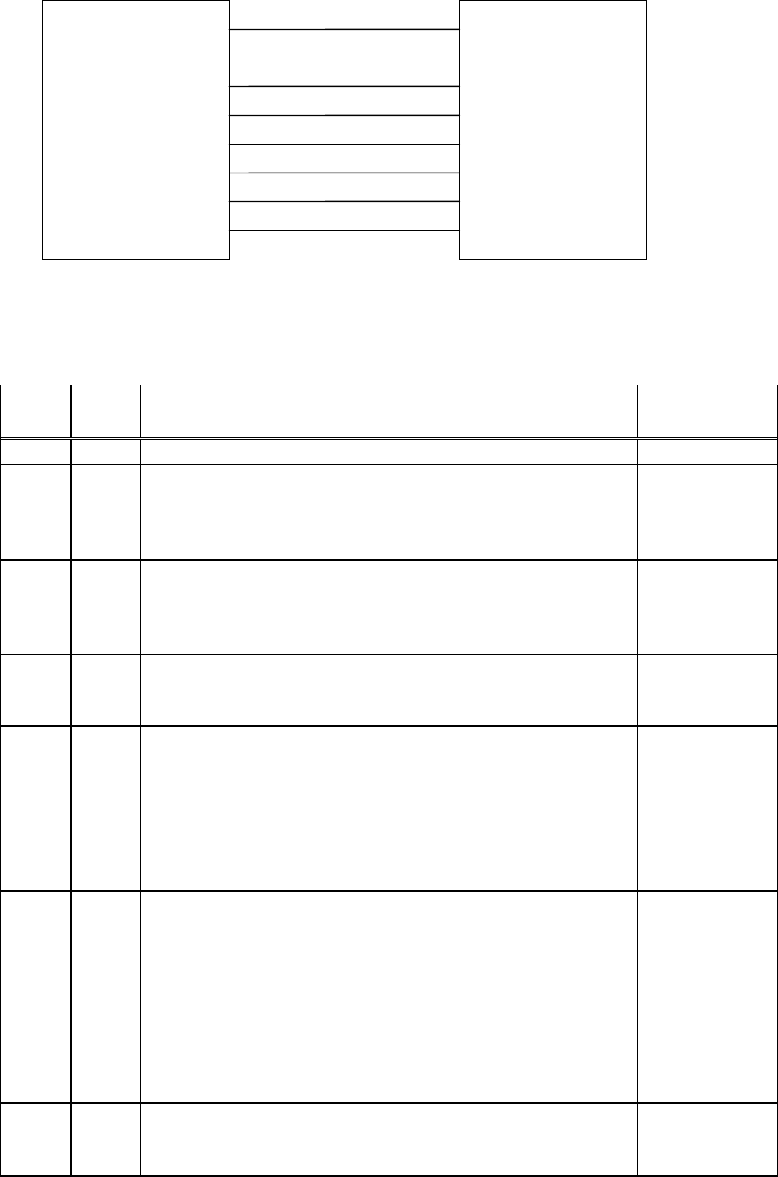
Printer Host
FG
TD
RD
RTS
CTS
DSR
SG
DTR