14 www.xilinx.com ML361 Virtex-II Pro Memory Board
UG060 (v1.2) November 8, 2007
Chapter 2: Architecture
R
Block Descriptions
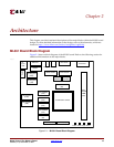
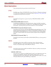
This section describes the major blocks of the ML361 board.
FPGA
The ML361 uses a Xilinx XC2VP20FF1152C-6 Virtex-II Pro device. This device is packaged
in a 1152-pin BGA package with a -6 speed grade. Refer to Appendix B, “FPGA Pinout,”for
a complete pinout of the Virtex-II Pro device.
Memories
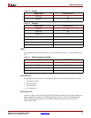
The ML361 board supports two types of memories: DDR SDRAM DIMM and DDR
SDRAM.
DDR SDRAM DIMM (Banks 6 and 7)
The DDR SDRAM DIMM used on the ML361 board is a 184-pin, 200 MHz, unbuffered,
non-ECC Micron MT4VDDT1664-AG-40BC3 device. This DIMM module has a 64-bit wide
data interface. The board also has provisions to interface to a 72-bit wide DIMM.
DDR SDRAM Components (Banks 2 and 3)
The ML361 board contains five 200 MHz DDR SDRAM components that provide a 72-bit
interface. These devices include four 16-bit Micron MT46V16M16TG-5B devices and one
MT46V32M8TG-5B DDR SDRAM devices. They are packaged in 66-pin TSOP packages.
They share a common address and control bus and have separate clocks and DQS/DQ
signals.
DDR SDRAM Component (Bank 1)
The ML361 board contains one 8-bit Micron MT46V32M8TG-5B device on the top bank of
the FPGA.
RS232
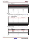
The ML361 board provides an RS232 serial interface using a Texas Instruments
MAX3221CDBR device. The maximum speed of this device is 250 Kb/s. The RS232
interface is accessible through a female DB9 RA connector.
Clocks
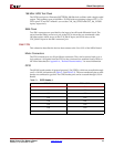
The ML361 board contains 166 MHz and 200 MHz LVDS clock oscillators and connectors
for external LVDS clock inputs.
200 MHz LVDS Clock
The LVDS clock is a Pletronics LV1145BW-200.0M oscillator with a differential output. The
oscillator runs at 200 MHz ± 50 PPM with an operating voltage of 2.5 V ± 5%. It is
terminated at the FPGA with a 100
Ω resistor. FPGA pins J17 and H17 in Bank 1 serve as the
CLK_200_LVDSP and CLK_200_LVDSN inputs, respectively.


