16 www.xilinx.com ML361 Virtex-II Pro Memory Board
UG060 (v1.2) November 8, 2007
Chapter 2: Architecture
R
II
DIP Switch
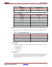
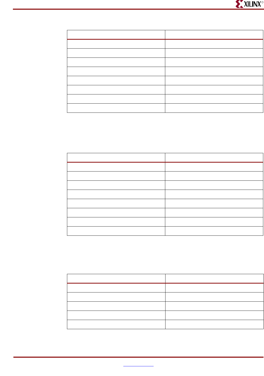
One eight-position DIP switch is connected to the FPGA I/Os as shown in Table 2-3. These
switches can be used to externally pull up or pull down any signal on the FPGA.
Seven-Segment Displays
Two seven-segment displays connect to the FPGA I/Os (see Table 2-4 and Table 2-5). The
red displays are active Low. The decimal points are not connected.
Table 2-2: GPIO Header 2
GPIO Pin # FPGA I/O Pin
G08 D30
G09 D29
G10 K23
G11 J23
G12 H22
G13 G22
G14 D26
G15 C26
Table 2-3: DIP Switch Connections
DIP Switch Input FPGA I/O Pin #
DIP1 G26
DIP2 H25
DIP3 G25
DIP4 J25
DIP5 K24
DIP6 J24
DIP7 F26
DIP8 E26
Table 2-4: Display 1
DIsplay Input FPGA I/O Pin #
Display1A C21
Display1B E21
Display1C F21
Display1D J20
Display1E K20


