62 www.xilinx.com ML361 Virtex-II Pro Memory Board
UG060 (v1.2) November 8, 2007
Chapter 4: Signal Integrity Recommendations and Simulations
R
Address/Control Signals
This subsection provides the address and control simulation results for the following
typical cases:
• With 45
Ω transmission line impedance measured at the first DDR component
• With 55
Ω transmission line impedance measured at the first DDR component
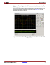
Address and Control Signals with 45Ω Transmission Lines Measured at the First
DDR Component
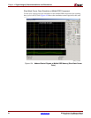
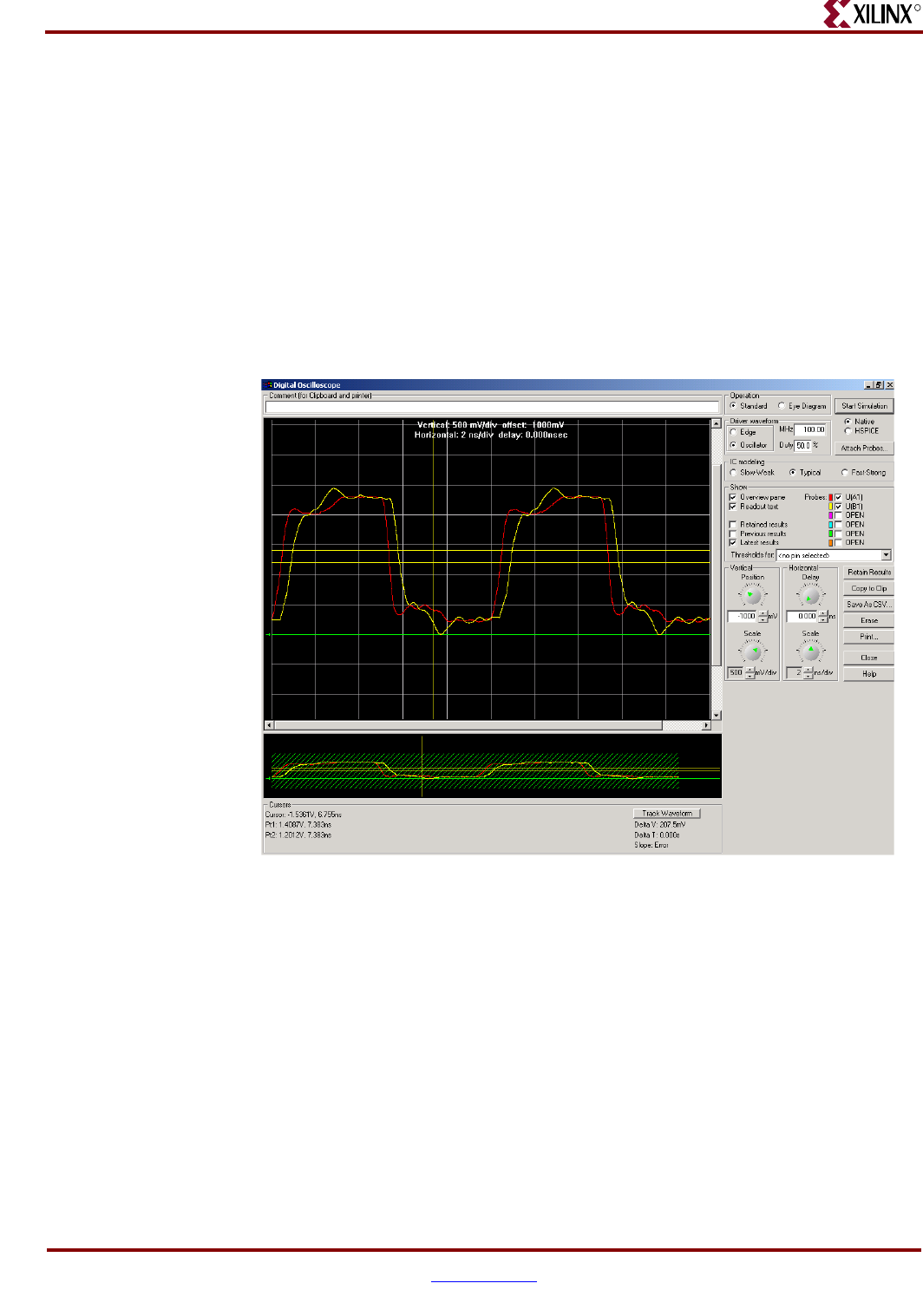
For the typical case simulation with a 45Ω transmission line impedance measured at the
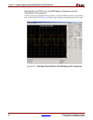
first DDR component, the resulting duty cycle is 48.94/51.2. Figure 4-32 shows the
simulation screen capture for this case.
X-Ref Target - Figure 4-32
Figure 4-32: Address/Control Signals with 45Ω Impedance Measured at First DDR
Component
ug060_c5_32_091003


