ML361 Virtex-II Pro Memory Board www.xilinx.com 17
UG060 (v1.2) November 8, 2007
Block Descriptions
R
LEDs
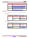
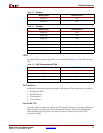
Four green LEDs connect to the FPGA I/Os as indicated in Table 2-6. The LEDs are active
Low.
Push Buttons
The ML361 board contains four momentary push buttons. Their functions are as follows:
• Program the FPGA
• Reset the board
• User function 1
• User function 2
Grounded I/Os
Unused I/Os are connected to GND in all FPGA banks. However, all memory banks have
eight unused I/Os connected to GND through 0
Ω resistors. These can be depopulated
when needed for test purposes. Care must be taken to not drive any unused I/Os
connected to GND.
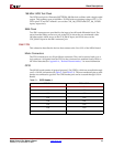
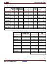
Display1F C24
Display1G D24
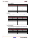
Table 2-5: Display 2
DIsplay Input FPGA I/O Pin #
Display2A D20
Display2B D21
Display2C F20
Display2D G20
Display2E K19
Display2F L19
Display2G C22
Table 2-4: Display 1
DIsplay Input FPGA I/O Pin #
Table 2-6: LED Connections to FPGA
LED # FPGA I/O Pin #
LED1 L18
LED2 K18
LED3 G18
LED4 F18


