


Modbus 485 and Modbus IP Protocols - UPS Systems
Liebert
®
IntelliSlot
®
Modbus/BACnet IP 134
Output Qualification Status output qualification status
Power Module Failure One or more conditions indicate a power module failure, service is required.
Power Module Fan Fault The Power Module has detected a fan fault.
Power Module Over Temperature The Power Module has detected an over temperature condition.
Power Module Shutdown - Over
Temperature
Power Module has shutdown due to over temperature.
Power Module Warning One or more power modules is reporting a warning condition.
Reboot After Delay
When a value is written to this point the output will be turned off after the specified
time has elapsed and then turned back on 10-30 seconds later.
Rectifier Failure Rectifier failure - rectifier is off
Replace Battery Module The Battery Module needs to be replaced.
Server Class The general classification for this system
Shutdown After Delay
When a value is written to this point the system will shutdown after the specified
time has elapsed and output will remain off.
System Capacity System capacity supported by the installed power modules.
System Date and Time The system date and time
System Input Black Out Count
The number of occurrences, since the last reset, where the input was not qualified
to provide power to the system
System Input Brown Out Count
The number of occurrences, since the last reset, where the system input voltage
has fallen below a pre-determined threshold for a specified amount of time
System Input Current Imbalance System Input Currents are Imbalanced
System Input Frequency The system input frequency
System Input Power Factor L1 The system input power factor for Line 1
System Input Power Factor L2 The system input power factor for Line 2
System Input Power Factor L3 The system input power factor for Line 3
System Input Power Problem The input is not qualified to provide power to the system
System Input RMS Current L1 The system input RMS current for Line 1
System Input RMS Current L2 The system input RMS current for Line 2
System Input RMS Current L3 The system input RMS current for Line 3
System Input RMS L1-L2 The System Input RMS Voltage between Line 1 and Line 2
System Input RMS L1-N The System Input RMS Voltage between Line 1 and Neutral
System Input RMS L2-L3 The System Input RMS Voltage between Line 2 and Line 3
System Input RMS L2-N The System Input RMS Voltage between Line 2 and Neutral
System Input RMS L3-L1 The System Input RMS Voltage between Line 3 and Line 1
System Input RMS L3-N The System Input RMS Voltage between Line 3 and Neutral
System Output Apparent Power L1 System output apparent power on Line 1
System Output Apparent Power L2 System output apparent power on Line 2
System Output Apparent Power The sum total apparent power of all system output phases
System Output Frequency The system output frequency
System Output Off The system output is off
System Output Pct Power L1 The system output power on Line 1 as a percentage of the rated capacity
System Output Pct Power L2 The system output power on Line 2 as a percentage of the rated capacity
System Output Power Factor L1 The system output power factor of Line 1
System Output Power Factor L2 The system output power factor of Line 2
System Output Power L1 The system output power on Line 1.
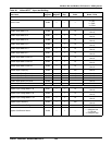
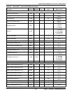
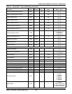
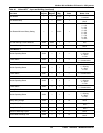
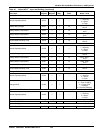
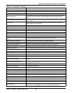
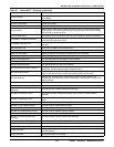
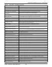
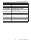
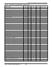
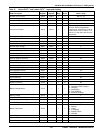
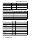
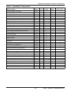
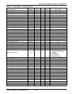
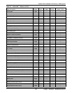
Table 45 Liebert APS
™
- Glossary (continued)
Data Label Data Description