


5 - 10
5
© 2003 - 2008 TOSHIBA TEC CORPORATION All rights reserved
e-STUDIO350/352/353/450/452/453
CONTROL PANEL
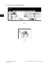
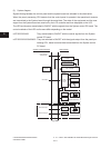
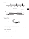
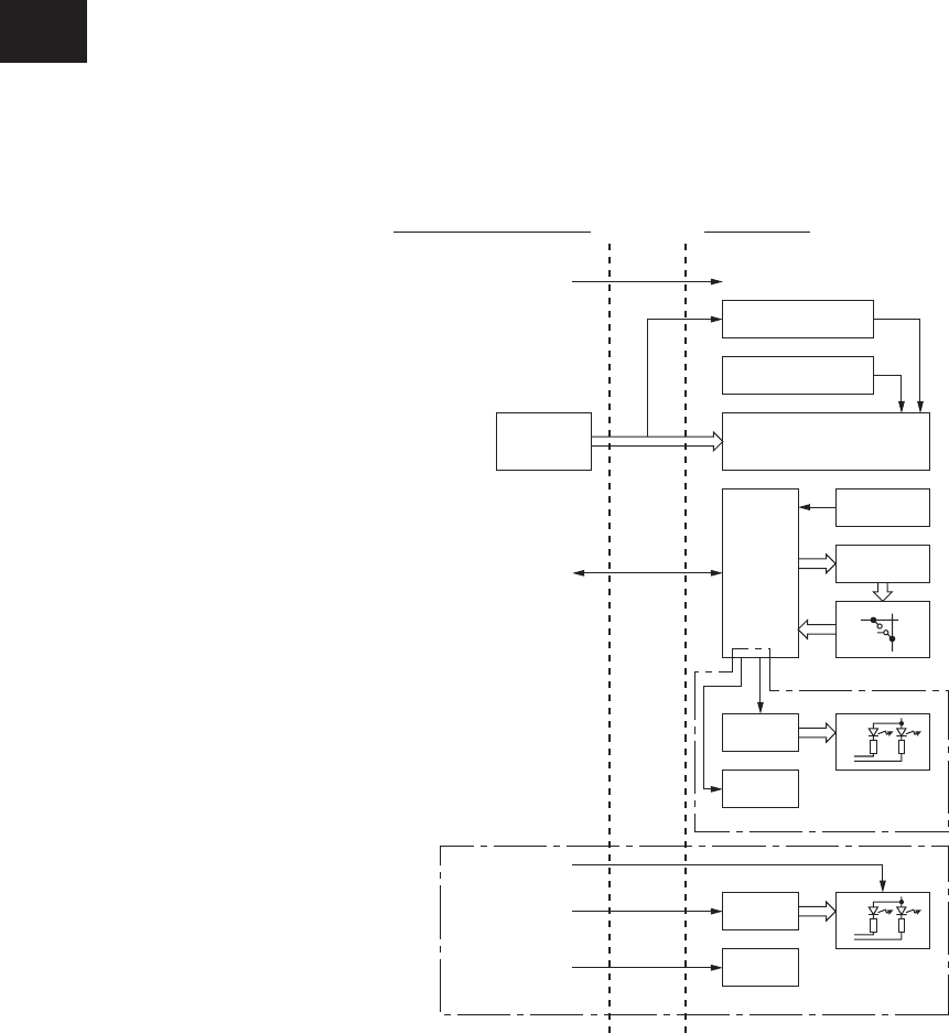
(3) System diagram
Signalsowingbetweenthecontrolpanelandthesystemboardareindicatedinthechartbelow.
When the panel processing CPU detects that the control panel is operated, the operational contents
are transmitted to the System board through the serial data. The state of the equipment and the mes-
sages from the System board are received by the LCD controller and then displayed on the LCD.
The LED and buzzers are switched to ON/OFF with the signals from the System control PC board. The
control methods of the LED and buzzers differ depending on the model:
e-STUDIO350/450: They are switched to ON/OFF with the control signals from the System
control PC board.
e-STUDIO352/353/452/453: They are switched to ON/OFF with the signals output from the panel pro-
cessing CPU, based on serial data transmitted from the System control
PC board.
Fig. 5-403
Inverter for
backlight
Contrast adjustment
circuit
LCD display
640 x 240 dots
LCD
controller
Analog
input
LED driver
Buzzer
Touch panel
Decoder
Hard-key matrix
LED
Serial data
Power ON/OFF
Reset signals
LED driver
Buzzer
LED
Buzzer ON signal
LED serial output
LED scan signal
e-STUDIO352/353/452/453
e-STUDIO350/450
Panel
processing
CPU
System control PC board
Control panel
07/11