


15 - 2
15
e-STUDIO350/352/353/450/452/453
POWER SUPPLY UNIT
© 2003 - 2008 TOSHIBA TEC CORPORATION All rights reserved
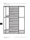
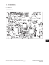
15.3 Output Channel
Thefollowingsareveoutputchannelswhicharenotlinkedwiththedoorswitch.
(1) +3.3V
+3.3VA : CN412 Pins 13, 14, 15 and 16
Output to the SYS board
+3.3VB : CN412 Pins 19 and 20
Output to the SYS board
+3.3VB : CN413 Pin 1
Output to the LGC board
+3.3VB : CN415 Pins 17 and 18
Output to the SLG board
(2) +5.1V
+5.1VA : CN412 Pins 24 and 26
Output to the SYS board
+5.1VB : CN412 Pin 25
Output to the SYS board
+5.1VB : CN413 Pins 3 and 4
Output to the LGC board, PFP/ LCF ( via LGC board ),
Bridge unit / Job separator / Offset tray (via LGC board)
+5.1VB : CN413 Pin 11
Output to the FIL board or FUS board
+5.1VB : CN415 Pins 5 and 6
Output to the RADF
+5.1VB : CN415 Pins 21 and 22
Output to the SLG board
+5.1VB : CN416 Pin 1
Outputtothenisher
(3) +12V
+12VA : CN412 Pin 7
Output to the SYS board
+12VB : CN412 Pin 5
Output to the SYS board
+12VB : CN413 Pin 7
Output to the LGC board
+12VB : CN415 Pin 15
Output to the SLG board
(4) -12V (e-STUDIO350/450 only)
-12VA : CN412 Pin 9
Output to the SYS board
-12VB : CN412 Pin 3
Output to the SYS board
(5) +24V (e-STUDIO350/450 only)
+24VB : CN413 Pin 13
Output to the FAX board
05/11