


e-STUDIO350/352/353/450/452/453
DRIVE SYSTEM
10
10 - 3
© 2003 - 2008 TOSHIBA TEC CORPORATION All rights reserved
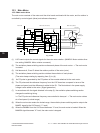
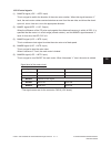
10.3.2 Control signals
(1) MAMCW signal (LGC
→
MTR: Input)
This is a signal to switch the direction of the main motor rotation. When this signal becomes “L”
level, the main motor rotates counterclockwise as seen from the rear side, and drives the devel
-
oper unit, drum, fuser unit, etc to the appropriate direction.
(2) MAMPL signal (MTR
→
LGC: Output)
When the difference of the FG pulse cycle against the reference frequency is within ±6.25%, it is
speciedthatthemotorisinalockrange(normalrotation),andthisMAMPLsignalbecomes“L”
level. At this time, the LED “D4” is lit.
(3) MAMCK signal (LGC
→
MTR: Input)
Thisisareferenceclocksignaltorotatethemainmotorataxedspeed.
(4) MAMBK signal (LGC
→
MTR: Input)
This is a signal to stop the main motor.
When it becomes “L” level, the main motor is braked.
(5) MAMON signal (LGC
→
MTR: Input)
This is a signal to turn ON/OFF the main motor. When it becomes “L” level, the motor is rotated.
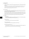
Signal level of the motor circuit
* The signal names are for the connector CN318 (LGC board).
Signal Level “H” Level “L”
MAMCW CCW direction CW direction
MAMPL Abnormal rotation Normal rotation
MAMCK Reference clock signal
MAMBK Brake OFF Brake ON
MAMON Motor OFF Motor ON