


2 - 33
2
e-STUDIO350/352/353/450/452/453
OUTLINE OF THE MACHINE
© 2003 - 2008 TOSHIBA TEC CORPORATION All rights reserved
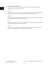
Fig. 2-525
Fig. 2-526
Fig. 2-527
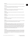
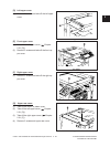
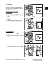
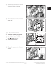
(3) Disconnect 14 connectors, 1 connector with
lockand1jointconnectorxedtothecase.
Fig. 2-524
Lock connector
Lock connector
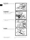
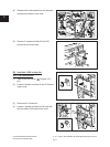
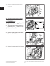
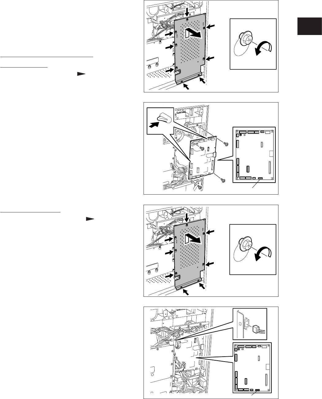
2.5.2 PC boards
Note:
When the PC board/HDD is replaced, refer to
each CAUTIONS of TROUBLESHOOTHING in
the SERVICE HANDBOOK.
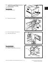
[A] Logic PC board (LGC board)
(A-1) LGC board
(1)
Take off the rear cover ( Chapter 2.5.1 [C]).
(2)
Loosen 8 screws and take off the LGC board
cover.
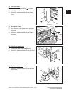
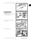
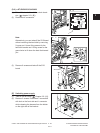
(3) Disconnect 14 connectors and 1 connector
with lock.
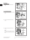
(4) Remove 4 screws and release 2 locking
supports. Then take off the LGC board.
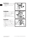
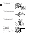
(A-2) LGC board unit
(1) Take off the rear cover ( Chapter 2.5.1
[C]).
(2) Loosen 8 screws and take off the LGC board
cover.
04/10