


13 - 15
e-STUDIO350/352/353/450/452/453
FUSER UNIT / PAPER EXIT SECTION
13
© 2003 - 2008 TOSHIBA TEC CORPORATION All rights reserved
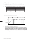
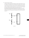
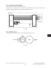
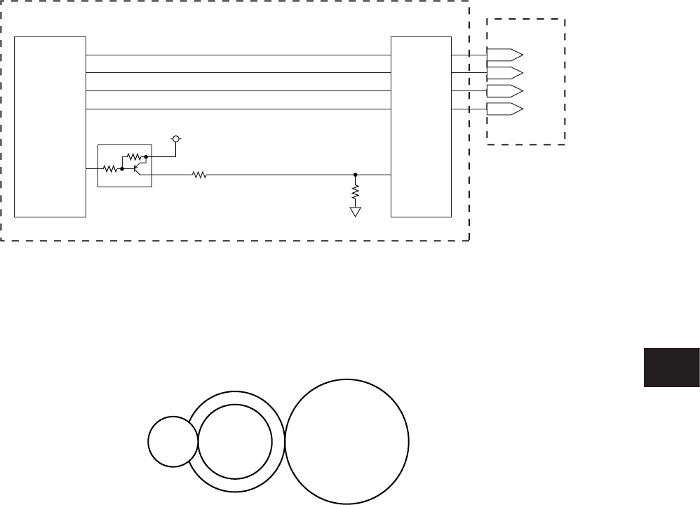
13.5 Control Circuit of Exit Motor
The following is the control circuit of the exit motor.
The exit motor is a stepping motor. The motor is turned ON/OFF and the direction of its rotation is
switched by controlling the output timing of pulse signal (A0·A1·B0·B1).
G14 G16 G20
G18
Exit motor Exit roller
(
ø15
)
PG10
PG12
PG11
PG13
Engine CPU
EXTMA
EXTMB
EXTMC
Exit Motor
EXTMD
EXTMA-0
EXTMB-0
EXTMC-0
EXTMD-0
STK672
A
AB
B
BB
A0
B0
A1
B1
VREF
PB1
+5V
LGC board
Fig. 13-501
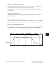
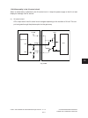
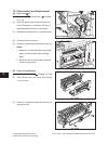
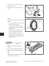
13.6 Exit Motor Drive
The diagram shown below is the layout of the driving gears of the exit roller.
Fig. 13-601
05/11