


13 - 4
13
e-STUDIO350/352/353/450/452/453
FUSER UNIT / PAPER EXIT SECTION
© 2003 - 2008 TOSHIBA TEC CORPORATION All rights reserved
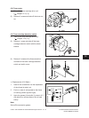
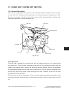
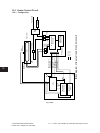
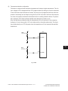
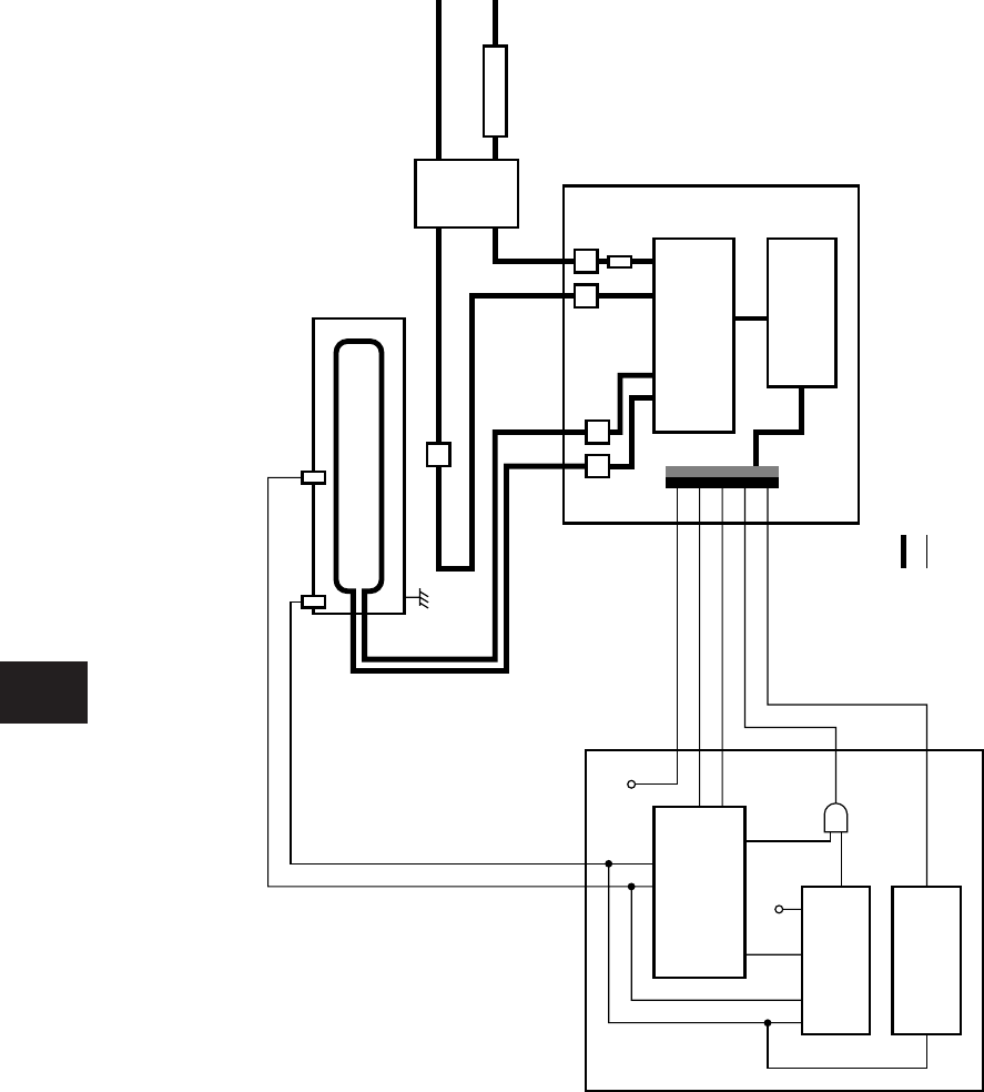
13.4 Heater Control Circuit
13.4.1 Conguration
Fig. 13-401
N
L
CPU
Temperature
control circuit
Upper limit
circuit
LGC
IH
5V SW
5V SW
Main
thermistor
Coil Fuser roller
Coil
output
Fuse
AC
input
Thermostat
Noise
filter
Breaker
Power code
Edge
thermistor
IH power source/
drive circuit
Control circuit
including CPU
Photocoupler
AC line
DC line
Power supply for
Photocoupler
Electric power setting
Error signal
IH1 ON signal
IH2 ON signal
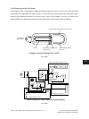
[
Block diagram of fuser unit and IH control circuit
]