


13 - 6
13
e-STUDIO350/352/353/450/452/453
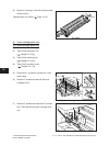
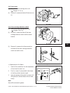
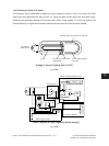
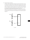
FUSER UNIT / PAPER EXIT SECTION
© 2003 - 2008 TOSHIBA TEC CORPORATION All rights reserved
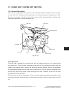
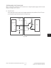
13.4.3 IH control circuit interface
The IH control circuit uses a photocoupler as an insulation against the secondary circuit.
The interface signals are as follows.
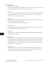
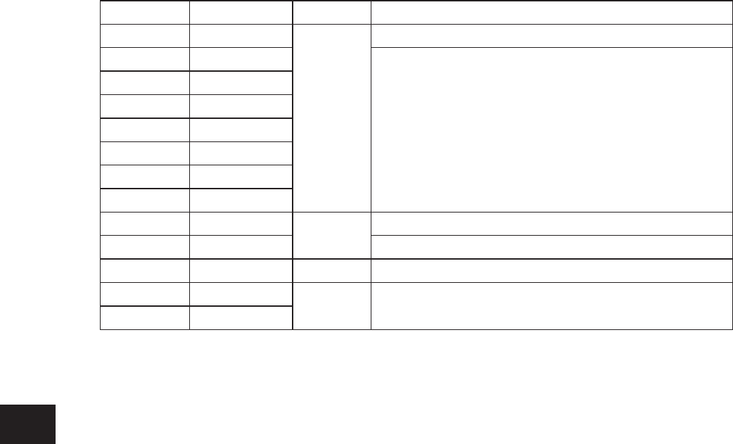
(*Note) IH status signal
• Whenthetemperature(duetoinsufcientcooling)oftheswitchingelement(IGBT)isabnormal:
“10: Coil is abnormal, IH FAN OFF”
→
After a certain period of time
→
Error [C480]
• When the upper limit of the power voltage is abnormal: “00: Initializing”
→
After a certain period
of time
→
Error [C470]
• When the lower limit of the power voltage is abnormal: “00: Initializing”
→
After a certain period
of time
→
Error [C470]
• Defective circuits
→
: “11: Abnormal circuit, IH coil abnormality”
→
Error [C490]
• Ready state after the initialization: “01: Ready”
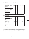
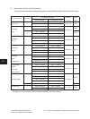
CN No. Name of signal Direction Denition
CN455-1 IH2 ON
LGC to IH
IH coil energization permitting signal
CN455-2 VDD
Switching signal of power setting
CN455-3 H1PWR1
CN455-4 H1PWR2
CN455-5 H1PWR3
CN455-6 H2PWR1
CN455-7 H2PWR2
CN455-8 H2PWR3
CN456-1 IH1 ON
LGC to IH
IH coil energization permitting signal
CN456-2
SG
CN456-3 NC - Not connected
CN456-4 H1ERR1
IH to LGC IH status signal (*Note)
CN456-5 H1ERR2