


6
6 - 8e-STUDIO350/352/353/450/452/453
SCANNER
© 2003 - 2008 TOSHIBA TEC CORPORATION All rights reserved
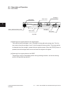
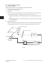
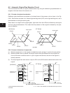
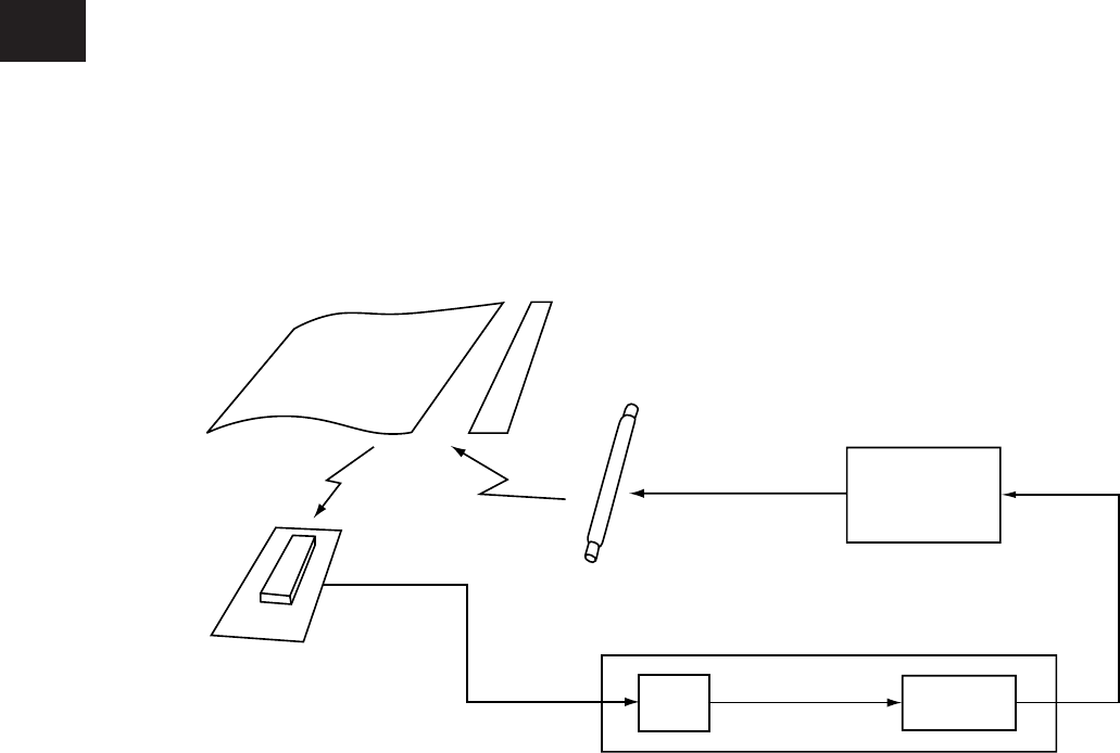
6.4 Control of Exposure Lamp
6.4.1 General description
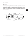
Control circuit for the exposure lamp consists of the following three blocks:
(1) Lighting device for the xenon lamp (Inverter)
Turns ON/OFF the exposure lamp.
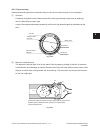
(2) CCD circuit
Thiscircuitconvertsthereectedlightamountfromtheoriginalsurfaceandtheshadingcorrec-
tion plate to electrical signals. The exposure amount is controlled in two ways:
(a)Whitereferenceformation-readsthereectedlightamountfromthewhiteshadingcorrection
plate
(b) Black reference formation - reads the light amount at the regulation position with the expo-
sure lamp lights OFF
(3) Image processing circuit
A series of image processes such as a gamma correction and a shading correction are applied
on the output signal from the CCD. The signal is then digitized and output from this circuit.
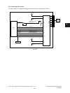
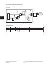
PWA-CCD
PWA-SLG
A/D
Fig. 6-401
Original
Shading correction plate
Exposure lamp (xenon lamp)
CCD
Lighting device
for xenon lamp
(Inverter)
Scanner
CPU
Image processing circuit