


e-STUDIO350/352/353/450/452/453
CONTROL PANEL
5
5 - 11
© 2003 - 2008 TOSHIBA TEC CORPORATION All rights reserved
LDON0
"L"
"L" 17
D7
Q3
IC
R3
(COPY)
5VL
LED
G
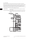
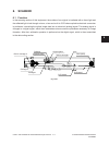
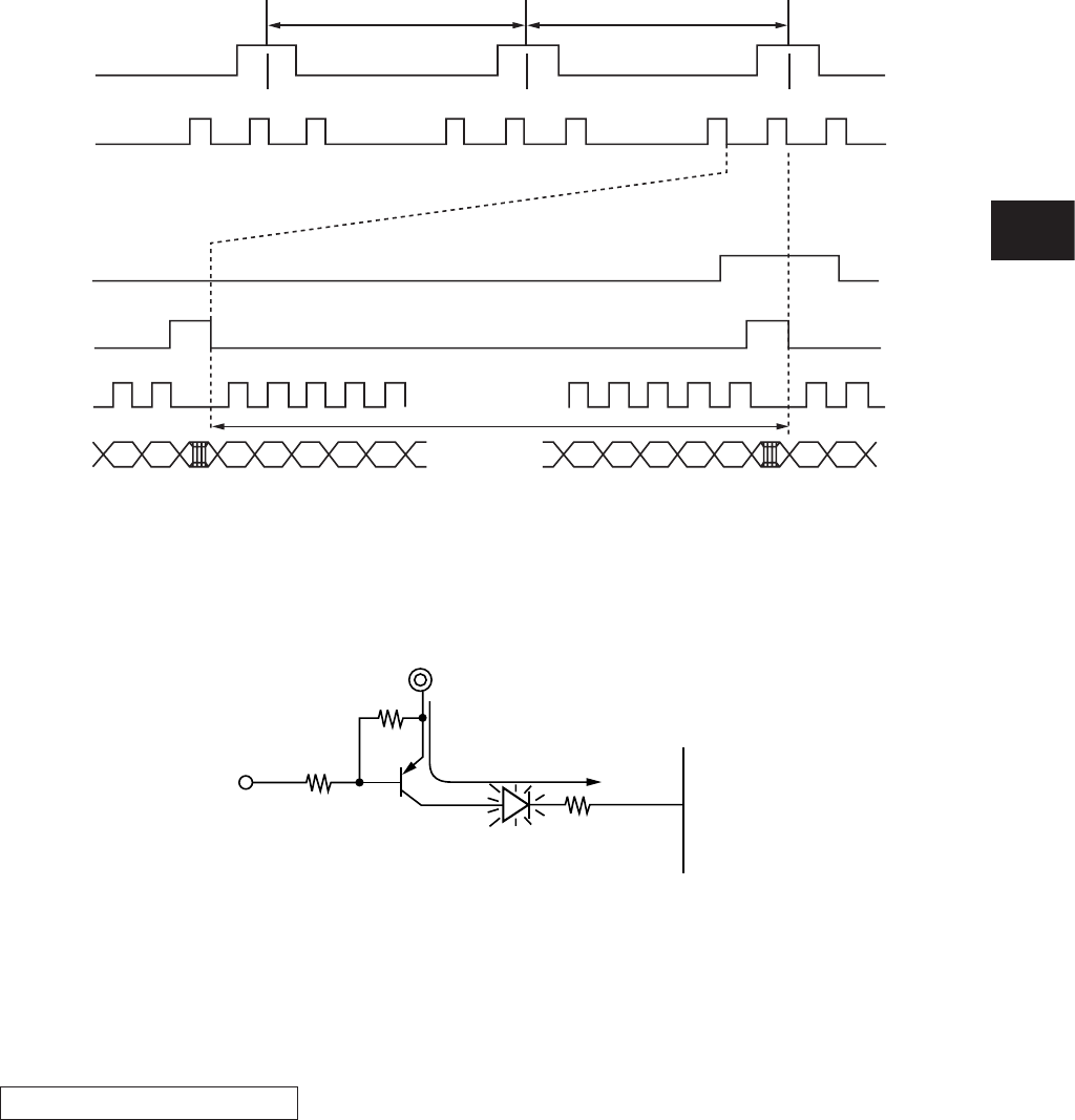
5.4.2 LED display circuit
(1) Method of LED display
ex) Displaying “COPY” .
Transistor is turned ON when the LDON 0 signal becomes “L” level.
Also,whenICpinchangesto“L”,thecurrentowsfrom5VLviathetransistortotheLED(“COPY”)
to turn ON the LED (“COPY”).
Current
Conditions to turn ON the LED
(a) The transistor (Q3) connected to the LED anode is ON.
(b) The output from the cathode side of the LED is “L” level.
The LED turns ON when the conditions (a) and (b) are met.
Fig. 5-405
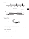
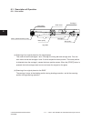
(4) Data Transmission
LOAD
FRAME
LOAD
240 1 2 240
CP x(640/4) pulses
1 2
240
1/tF1/tF
1 2
FRAME
D0-D3
CP
Fig. 5-404