


e-STUDIO350/352/353/450/452/453
LASER OPTICAL UNIT
8
8 - 9
© 2003 - 2008 TOSHIBA TEC CORPORATION All rights reserved
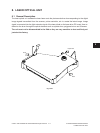
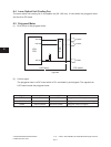
Fig. 8-601
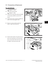
8.6 Disassembly and Replacement
[A] Laser optical unit
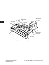
(1) Take off the receiving tray
( Chapter 2.5.1 [H]).
(2) Take off the front left cover
( Chapter 2.5.1 [B]).
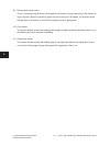
(3) Disconnect the connector with lock (CN206)
and connector (CN207) on the LRL PC
board.
(4) Disconnect the joint connector between the
laser unit fan and polygonal motor.
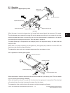
(5) Remove 1 screw on the front side and
loosen 1 screw on the rear side.
Fig. 8-602
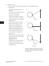
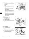
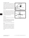
(6) Stand the laser optical unit against the rear
side of the equipment by moving the relay
stay to the rear side. Be careful not to fold
the cable on the relay stay rear side.
Fig. 8-603