


8 - 10
8
e-STUDIO350/352/353/450/452/453
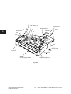
LASER OPTICAL UNIT
© 2003 - 2008 TOSHIBA TEC CORPORATION All rights reserved
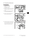
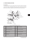
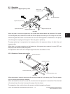
(7) Remove 3 screws with spring. Lift up the
laser optical unit, avoiding contact with the
laser unit fan.
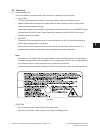
Note:
1.Donotleavengerprintsorstainonthe
slit glass.
2. Laser optical unit is a precise apparatus.
Handle the unit with extra care not to
shock or vibrate it.
3. Never attempt to disassemble the unit in
theeldsinceitisverysensitivetothe
dust and stain.
4.Wheninstalling,xthelaseropticalunit
with the screws securely by matching the
bosses on the bottom of the unit with the
holes of the frame.
Fig. 8-604
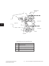
Fig. 8-605
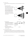
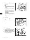
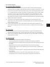
[C] LRL PC board
(1) Take off the receiving tray
( Chapter 2.5.1 [H]).
(2) Disconnect 2 connectors with lock (CN204
and CN206) and 1 connectors (CN207).
(3) Remove 1 screw. Take off the LRL PC board
by releasing 2 locking supports.
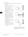
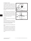
[B] Laser unit fan
(1) Take off the receiving tray
( Chapter 2.5.1 [H]).
(2) Disconnect 1 connector.
(3) Remove 2 screws and take off the laser unit
fan.
Fig. 8-606
04/10