


12 - 6
12
e-STUDIO350/352/353/450/452/453
DEVELOPMENT SYSTEM
© 2003 - 2008 TOSHIBA TEC CORPORATION All rights reserved
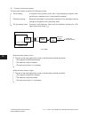
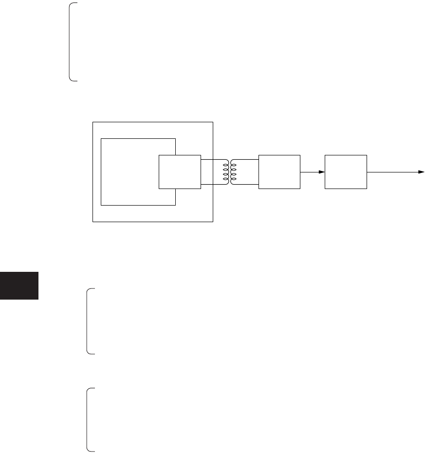
Drive
winding
Detection
winding
DC
conversion
circuit
Auto-toner
output
To the main
CPU
(
LGC board
)
V
ATS
Magnetic circuit
Magnetic resistance
(
Developer material
)
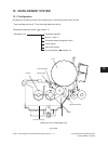
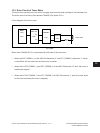
(2) Function of auto-toner sensor
The auto-toner sensor consists of the following circuits:
· Drive winding : A magnetic head (primary side) with a high-frequency magnetic field,
which forms a magnetic circuit in the developer material.
· Detection winding : Receives the change in the magnetic resistance of the developer material
through the magnetic circuit (secondary side).
· DC conversion circuit : Converts a high-frequency output from the detection winding into a DC
signal (auto-toner output V
ATS
).
When the toner density is low—
The ratio of the toner against the carrier in the developer material decreases.
→
The magnetic resistance decreases.
→
The detection output increases.
→
The auto-toner output V
ATS
increases.
When the toner density is high—
The ratio of the toner against the carrier in the developer material increases.
→
The magnetic resistance increases.
→
The detection output decreases.
→
The auto-toner output V
ATS
decreases.
Fig. 12-402