iie-STUDIO350/352/353/450/452/453
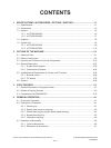
CONTENTS
© 2003 - 2008 TOSHIBA TEC CORPORATION All rights reserved
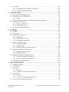
4.4 Flow Chart ..........................................................................................................................4-12
4.4.1 Immediately after the power is turned ON ..............................................................4-12
4.4.2 Automatic paper feed copying ................................................................................4-14
5. CONTROL PANEL ........................................................................................................5-1
5.1 Control Panel and Display Panel .........................................................................................5-1
5.2 Items Shown on the Display Panel ......................................................................................5-2
5.2.1 Display .....................................................................................................................5-3
5.3 Relation between the Equipment State and Operator’s Operation ......................................5-8
5.4 Description of Operation ......................................................................................................5-9
5.4.1 Dot matrix LCD circuit ...............................................................................................5-9
5.4.2 LED display circuit ..................................................................................................5-11
5.5 Disassembly and Replacement ..........................................................................................5-12
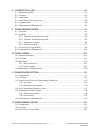
6. SCANNER .....................................................................................................................6-1
6.1 Function ...............................................................................................................................6-1
6.2 Construction .........................................................................................................................6-2
6.3 Description of Operation ......................................................................................................6-4
6.3.1 Scan motor ................................................................................................................6-4
6.3.2 Scanning drive circuit ...............................................................................................6-5
6.3.3 Initialization at power-ON .........................................................................................6-7
6.4 Control of Exposure Lamp ...................................................................................................6-8
6.4.1 General description ...................................................................................................6-8
6.4.2 Exposure lamp ..........................................................................................................6-9
6.4.3 Control circuit for the exposure lamp ......................................................................6-10
6.5 General Description of CCD Control ..................................................................................6-11
6.5.1 Opto-electronic conversion .....................................................................................6-11
6.5.2 Shading correction ..................................................................................................6-11
6.6 Automatic Original Size Detection Circuit ..........................................................................6-12
6.6.1 Principle of original size detection ...........................................................................6-12
6.6.2 Process of detection of original size .......................................................................6-12
6.7 Disassembly and Replacement ..........................................................................................6-16
7. IMAGE PROCESSING ..................................................................................................7-1
7.1 General Description .............................................................................................................7-1
7.2 Conguration ........................................................................................................................7-3
7.3 SLG Board ...........................................................................................................................7-4
7.3.1 Features ....................................................................................................................7-4
7.3.2 Functions of image processing circuit .......................................................................7-5
7.4 LGC Board ...........................................................................................................................7-9
7.4.1 Features ....................................................................................................................7-9
7.4.2 Functions of image processing circuit .......................................................................7-9
7.5 Laser Driving PC Board (LDR board) .................................................................................7-10


