Installation 2-9
device or cable that connects the input signals on one device
to the output signals on another device) is often required since
both the printer and the print server are usually DTE devices.
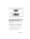
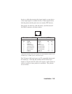
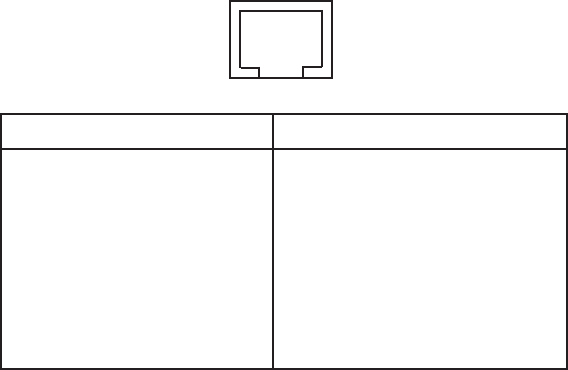
The pinouts for the Pony 100, XConnect, and XConnect II
Lite RJ45 connector are shown below:
RJ45 DTE DCE
pin Signal Signal pin pin
1 RTS out* CTS in 5 4
2 DTR out* DSR in 6 20
3 Transmit Data Receive Data 3 2
4 Transmit return Signal Ground 7 7
5 Receive Return Signal Ground 7 7
6 Receive Data Transmit Data 2 3
7 DSR in* DTR out 20 6
8 CTS in* RTS out 4 5
*XConnect II models with serial numbers less than 40500 have RTS on pin
8, DTR on pin 7, DSR on pin 2, and CTS on pin 1.
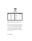
The XConnect 100 serial ports use PC-compatible 9-pin male
D-connectors. Note that the standard off-the-shelf 9-pin
female to 25-pin male PC cables will require a null modem in
order to connect to most printers or terminals. The pinouts
are as follows:
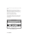
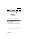
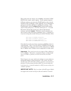
Print Server (RJ45)
1 2 3 4 5 6 7 8
Printer (DB25)


