


• 2-49 • RMAN-QLS-002 rev. A Repair Procedures
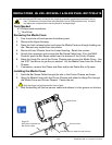
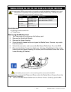
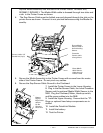
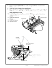
7. Remove and retain the Screws securing the Media Guide Plate Assembly to the
Printer.
8. Remove the optional Media Width Sensor. If the Printer is equipped with the
Media Width Sensor, pull the sensor cable free of the Printer Frame.
9. Remove the Media Guide Plate Assembly. Rock the Media Guide Plate Assem-
bly forward and then lift it away from the Printer Frame. Keep the Gap Sensor
Cable with the Media Guide Plate Assembly. Retain all components.
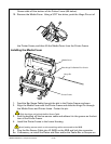
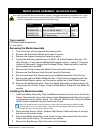
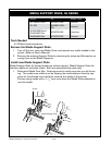
1. Fold the Gap Sensor Cable and dress it through the slot near the side of the
Printer Frame.
2. Dress the (optional) Media Width Sensor Cable through the slot near the side of
the Printer Frame.
3. Insert the Pinion Gear in the round hole that accesses the rack gear and slip the
Media Guide Plate Assembly into the slot in the bottom of the Printer Frame.
The tab on the bottom of the Media Guide Plate Assembly ts into the slot in
the bottom of the printer frame. Push the Media Guide Plate Assembly against
the Printer Frame.
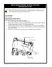
4. Insert screws from the motor side of the Printer Frame and secure the Media
Guide Plate Assembly to the Printer Frame. Do not pinch any cables.
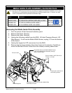
5. Plug the Gap Sensor cable and (optional) Media Width Sensor Cable into the
MLB and lock the connectors.
6. Make sure that the Media Supports move freely with the Latch open.
7. Install the MLB and Printer Frame into the chassis.
8. Plug the keypad or LCD cables into the MLB.
9. Install the chassis and Printer Frame to the Lower Housing.
10. Install the Upper Housing.