


RMAN-QLS-002 rev. A Repair Procedures • 2-102 •
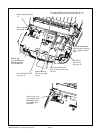
Removing the MLB
1. Turn the printer off and remove the battery pack.
2. Remove the QuickLink Module.
3. Remove the Upper Housing.
4. Remove the Keypad.
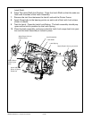
5. Unplug all cables from the MLB.
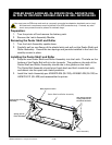
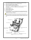
6. Remove the remaining Screw securing the MLB and pull the MLB out of the
printer.
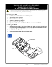
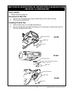
Installing the MLB
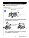
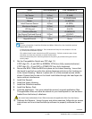
1. Plug the Head Open Switch cable and the Media Width Sensor (optional) cables
into the bottom of the MLB.
mLb, QL 320- an16861-018, RK18234-1;
QL 320 pLuS- RK18465-002
QL 320 coSt Reduced- RK18465-006
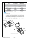
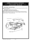
2. Plug the remaining cables into the MLB per the following table:
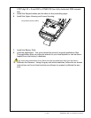
Notes:
1 . For ease of assembly, install the Printhead and Motor Cables first, then install the op-
tional Media Width Cable.
2 . Connectors for cables are polarized. The connectors will only fit in one direction. Do
not try to force the connectors in place.
3. Flex cables install in zero insertion force (ZIF) connectors. Pull the connector open, insert
the cable, and close the connector to retain the flex cable.
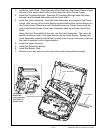
4. Dress all cables way from mounting bosses so they won’t get pinched during the next as-
sembly steps.
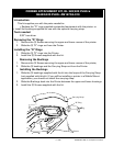
3. Lower the MLB into the Lower Housing. Insure that the board is pushed up un-
From # of connections CPU Connector #
Head Open Switch 2 J1 (HEAD)(bottom of board)
Bar Sensor 3 (Flex) J2 (BAR)
Printhead 28 (Flex) J3 (PRINTHEAD)
Motor 4 J4 (MOTOR)
Label Presence Sensor 4 (Flex) J5 (PEEL)
Membrane Keypad 8 (Flex) J6 (KEYPAD)
LCD Keypad 10 (Flex) J8 (LCD)
QuickLink Module J9 (MODULE)
Gap Sensor/Printhead Ground 5 (Flex) J10 (GAP)
Media Width Sensor (optional) 3 J11 (WIDTH)(bottom of board)
Keypad Ground 1 (Flex) Screw
continued
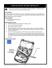
You must use an ESD strap and work at a properly grounded workstation (antistatic mat or tray).
All electronic components must be placed on an ESD protective tray. If stored, any elec-
tronic components must be placed in antistatic bags.