


• 2-87 • RMAN-QLS-002 rev. A Repair Procedures
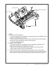
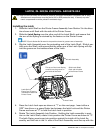
Installing the Printhead
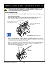
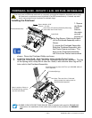
1. Secure
the Static
Cable.
Secure
the static
ground
section of
the Gap Sensor Cable to the back
of the Printhead Assembly with a
Screw.
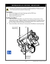
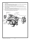
2. Locate the Printhead Assembly.
Slide the Printhead Assembly into
the Printer Frame as shown. The
ears on the Printhead Assembly
will t into the Printer frame where
shown. Dress the Printhead Cable as shown.
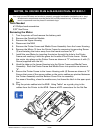
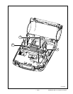
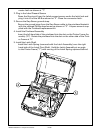
3. Install the Latch Shaft. Slide the Shaft, Latch into the Printer Frame.
4. Install the Printhead Springs. Snap the Printhead Springs into position. The leg
of the Spring with a loop will t over the Shaft, Latch and the other leg will t
into a slot in the Printhead Assembly.
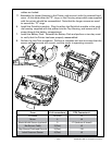
Printhead Springs
Note: Location of loop on
Printhead Spring secures
over the Latch Shaft.
Press Springs into place with Tool p/n AU16259-1(Use of
tool is optional)
Note: This end of the Printhead
Spring snaps into mating slots on
the Printhead Assembly.
Printhead Assembly
Note: Ears of Printhead Assembly Mounting
plate slide into Printer Frame.
Screw #4-40 x 3/16”
Torque = 5 in-lbs
Latch Shaft
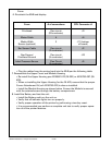
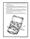
You must use an ESD strap and work at a properly grounded workstation (antistatic mat or tray).
All electronic components must be placed on an ESD protective tray. If stored, any elec-
tronic components must be placed in antistatic bags.
P/n CL16985-3 CBL FLEX CRKT SHLD QL4 LBL SEN is included with repair kit RK18465-003.
Instructions for installation of this cable are included in the procedure for AN16861-
015
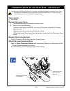
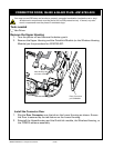
pRinthead, QL320 - RK18277-1 & QL 320 pLuS- RK18465-003