


• 2-85 • RMAN-QLS-002 rev. A Repair Procedures
5
5
5
5
4
3
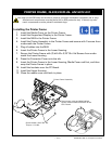
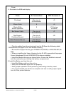
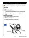
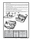
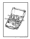
From # of connections CPU Connector #
Printhead 28 (Flex) J3
Motor 4 J4
Media Width Sensor (optional) 3 J11 (bottom of board)
Bar Sensor Cable 3 (Flex) J2
Gap Sensor/Printhead Ground 5 (Flex) J10
Label Presence Sensor 4 (Flex) J5
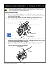
J4
J3
J10
J11
J5
J2
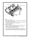
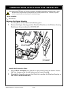
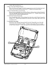
cables are locked.
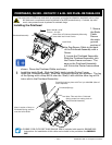
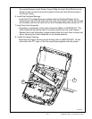
11. Assemble the Upper Housing to the Printer, and secure it with the retained hard-
ware. At this time either the “D” rings, or the Carrying strap which was supplied
with the printer should be reassembled. Note that the longer screws are used
to secure the “D” rings.
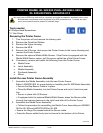
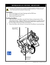
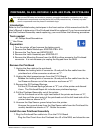
6. Install the QuickLink module. Plug the either the QuickLink module or the mod-
ule housing supplied with the printer into the Top Housing, and secure with (1)
screw through the battery compartment.
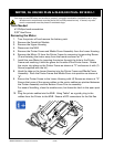
7. Install the Battery Pack. Reinstall the Battery Pack and perform a two-key reset
to verify that the Printer has been properly reassembled.
8. Perfom the Unit Test procedure. Perform a complete unit test to ensure that the
sensor calibrations are still correct, and the motor is operating correctly.