


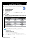

RMAN-QLS-002 rev. A Repair Procedures • 2-98 •
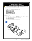
Preparation:
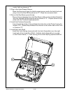
1. Turn the printer off and remove the battery pack.
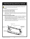
2. Remove the Latch Assembly Module
Removing the Peeler Shaft and Roller
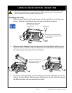
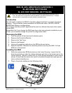
1. Turn the Latch Assembly upside down.
2. Carefully pull on one ange of the plastic latch and pull out the Peeler Shaft and
Roller Assembly. Ensure the two springs and journals installed in the Latch As-
sembly remain in place.
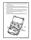
Installing the Peeler Shaft and Roller
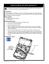
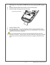
1. Snap the new Peeler Shaft and Roller Assembly into the Latch. The tabs on the
bottom of the Peeler Bail will sit in the Journals. The guides on the side of the
Peeler Shaft and Roller Assembly should ride in the guides on the Latch.
The Peeler Bail Assembly should pivot freely back and forth inside the Latch,
and detent into the open and closed positions.
2. Install the Latch Assembly per AN16972-004 (QL 220); AN16861-025 (QL 320) or
AN16753-011 (QL 420) and reassemble the printer.
peeLeR Shaft & RoLLeR, QL 220/220 pLuS- an16972-006;
QL 320/ QL 320 pLuS- an16861-026 & QL 420- an16753-024
You must use an ESD strap and work at a properly grounded workstation (antistatic mat or tray).
All electronic components must be placed on an ESD protective tray. If stored, any elec-
tronic components must be placed in antistatic bags.
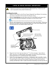
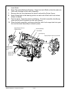
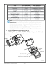
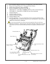
Peeler Shaft and Roller Assembly
Note position of “ears”
Journal (part of Latch
Assembly )
Spring (part of
Latch Assembly)
This feature will ride
in the guide slots on
the side of the Latch
Latch Assembly