


• 2-91 • RMAN-QLS-002 rev. A Repair Procedures
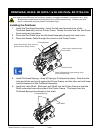
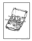
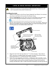
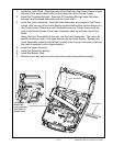
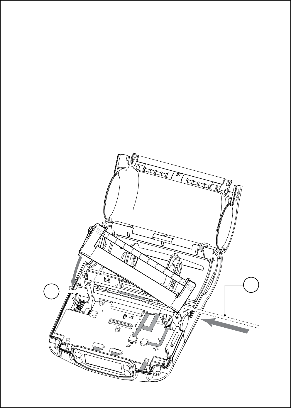
the vertical feature on the Printer Frame. Slide the Latch Pivot Shaft into the
Printer Frame so that the end of the shaft is ush with the left hand side of
the Printer Frame.
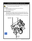
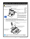
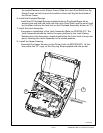
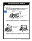
6. Install the Printhead Springs
Install the (2) Printhead Springs supplied with the Printhead Repair kit by
pressing the end with the loop over the Latch Pivot Shaft, and the short hook
on the other end into the heat sink on the Printhead Assembly (shown at “2”).
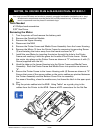
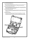
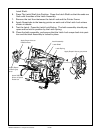
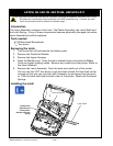
7. Install the Latch Assembly
Complete re-installation of the Latch Assembly (Refer to AN16753-011) The
Latch Assembly should be held in the open position by the Latch Spring.
Rotating the Latch Assembly closed should allow the Latch Lock to snap into
place, retaining the Latch Assembly in the closed position.
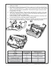
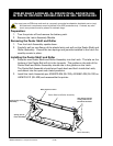
8. Install the Upper Housing
Assemble the Upper Housing to the Printer (refer to AN16753-007). At this
time either the “D” rings, or the Carrying Strap supplied with the printer
continued
1
2