


• 2-105 • RMAN-QLS-002 rev. A Repair Procedures
continued
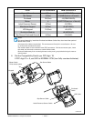
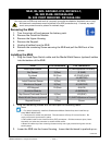
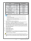
From # of connections CPU Connector #
Head Open Switch 2 J1 (HEAD)(bottom of board)
Bar Sensor 3 (Flex) J2 (BAR)
Printhead 28 (Flex) J3 (PRINTHEAD)
Motor 4 J4 (MOTOR)
Label Presence Sensor 4 (Flex) J5 (PEEL)
Membrane Keypad 8 (Flex) J6 (KEYPAD)
LCD Keypad 10 (Flex) J8 (LCD)
QuickLink Module J9 (MODULE)
Gap Sensor/Printhead Ground 5 (Flex) J10 (GAP)
Media Width Sensor (optional) 3 J11 (WIDTH)(bottom of board)
Keypad Ground 1 (Flex) Screw
Notes:
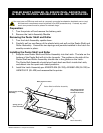
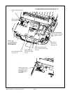
For ease of assembly, install the Printhead and Motor Cables first, then install the optional
Media Width Cable.
Connectors for cables are polarized. The connectors will only fit in one direction. Do not
try to force the connectors in place.
Flex cables install in zero insertion force (ZIF) connectors. Pull the connector open, insert
the cable, and close the connector to retain the flex cable.
Dress all cables away from mounting bosses so they won’t get pinched during the next as-
sembly steps.
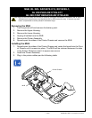
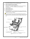
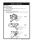
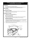
3. Set the Compatibility Switch per PCC digit 10
If PCC digit 10 = 0, set SW1 to NORMAL CCW (turn fully counterclockwise ).
If PCC digit 10 = S, set SW1 to OTHER CW (turn fully clockwise).
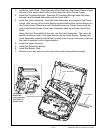
4. Secure the MLB. Slide the MLB into place on the Lower Housing. Insure that
the board is pushed up under the retainer features and sits on the locating pin
in the Lower Housing. Secure in place with (1) of the retained screws where
shown. Ensure that the tab on the Latch Lock slides through the head open de-
tector without interference.
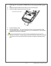
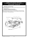
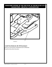
5. Install the Keypad.
6. Install the Upper Housing.
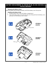
7. Install the QuickLink module.
8. Install the Battery Pack.
9. Load the application. You must reload the printer’s original application les.
The application les can either be stored on your local system or can be down-
loaded from the factory’s database.
You must have authorization from Zebra to access the application files from the factory.
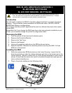
10. Calibrate the Sensors. Using the gray and white swatches, follow the on-screen
instructions on the unit test and set-up software to properly calibrate the sen-
sors.