


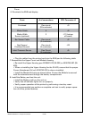

RMAN-QLS-002 rev. A Repair Procedures • 2-88 •
You must use an ESD strap and work at a properly grounded workstation (antistatic mat or tray).
All electronic components must be placed on an ESD protective tray. If stored, any elec-
tronic components must be placed in antistatic bags.
Introduction
Refer to the Troubleshooting techniques in the front section of this manual and the QL
User’s Manual to determine if the Printhead should be replaced. If you have ascertained
that the Printhead Assembly needs replacing, you must follow the following procedure:
Tools needed
#1 Phillips Head Screwdriver.
3
/
32
” Hex Driver
Preparation
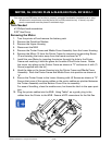
1 Turn the printer off and remove the battery pack
2 Remove the Radio Module per AN16753-018 & -019
3 Remove the Top Cover per AN16753-007
4 Remove the Latch Assembly per AN16753-011
5. Remove the Mounting Screws from the MLB to allow access to the Printhead
connector. It is not necessary to unplug the Keypad from the MLB.
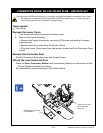
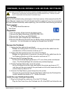
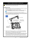
Remove the Printhead
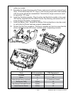
1. Unplug the ex cable to the printhead.
Release the locking latch of connector J3 and pull the ex cable from the
printhead out of the connector as shown at “1”.
2. Unplug the label present sensor from the C.P.U. Board.
Release the locking latch of connector J5 and pull the ex cable from the La-
bel Presence Sensor out of the connector as shown at “2”.
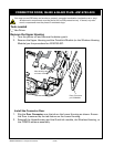
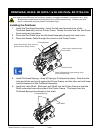
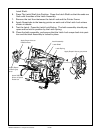
3. Remove the (2) Printhead Springs.
Pull the (2) Printhead Springs (shown at “3”) out of the printer and discard
them. The Printhead Repair kit includes new printhead springs.
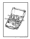
4. Pull the Printhead Assembly out of the printer.
Lift the Printhead out of the right hand side of the printer as shown at “4”,
and then pull the pivot point of the printhead out of the left hand side of the
printer frame as shown at “5”.
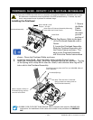
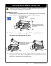
5. Unscrew the Gap Sensor ground strap from the printer.
Unscrew the ground strap from the Gap Sense cable from the Printhead As-
sembly heatsink as shown at “6”. Retain the screw.
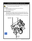
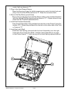
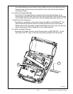
Install the new Printhead Assembly
1. Plug the Printhead Flex cable into J3 on the C.P.U. Board
Plug the Flex Circuit from the Printhead into J3 of the MLB, and close the con-
pRinthead, QL 420- RK18252-1 & QL 420 pLuS- RK17735-004