


• 2-95 • RMAN-QLS-002 rev. A Repair Procedures
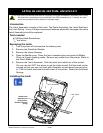
You must use an ESD strap and work at a properly grounded workstation (antistatic mat or tray).
All electronic components must be placed on an ESD protective tray. If stored, any elec-
tronic components must be placed in antistatic bags.
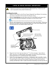
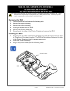
Installing the Latch
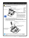
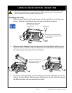
1. Slide the Latch Shaft in the Printer Frame until the end is ush to the frame as
shown. Slide the Latch Spring over the end of the Shaft as shown.
Latch, QL 320/ QL 320 pLuS- an16861-025
Note: leg of the Torsion Spring
is captured by this feature on the
Printer Frame.
Slide the Shaft, Latch until
this end is ush with the
Printer Frame.
Latch Spring
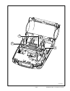
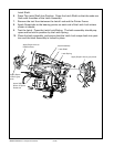
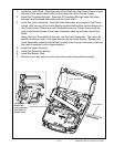
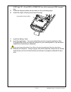
2. Slide the Latch Assembly over the right end of the Latch Shaft, holding it at an
angle as shown, and then rotate the Latch down into the Printer Frame assem-
bly, capturing the other leg of the Latch Spring.
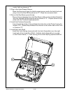
Slide the Latch Shaft back
into place until this end is
ush with the Latch.
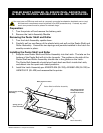
4. Secure the Latch Assembly. Line the left side of the latch assembly up with the
hole for the Latch Shaft. Slide the Latch Shaft back to the left until both ends of
the Shaft are ush with the outside of the Latch.