


RMAN-QLS-002 rev. A Repair Procedures • 2-50 •
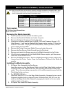
Kit p/n Description
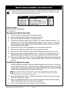
RK16823-043 KIT RPR QL320 MEDIA GUIDE/MW
RK18460-1 KIT RPR QL3 MEDIA GUIDE W/BELT
RK18461-1 KIT QL3 MEDIA GUIDE LNL W/BELT
RK18462-1 KIT QL3 MEDIA GUIDE MW W/BELT
RK18463-1 KIT QL3 MEDIA GUIDE LNL MWBELT
Tools needed
#1 Phillips Head Screwdriver.
3/32” hex driver
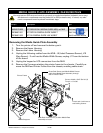
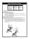
Removing the Media Assembly
1. Turn the printer off and remove the battery pack.
2. Remove the QuickLink Module and retain the parts.
3. Remove the Upper Housing and retain the parts.
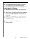
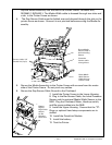
4. Unplug the following cables from the MLB: J5 (Label Presence Sensor), J10
(Gap Sensor). If unit has the Media Width Sensor option, unplug J11 from the
bottom of the board. Unplug the Printhead, Motor, Head-up switch, and Bar
sense cables from the MLB.
5. Remove the Printer Frame and Media Cover and retain the parts.
6. Remove the Gap Sensor Cable Ground from the Printhead.
7. Remove and retain the Screws securing the Media Assembly to the Printer.
8. If the Printer is equipped with the Media Width Sensor option, pull the sensor
cable free of the Printer Frame.
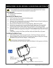
9. Remove the Media Assembly. Rock the Media Assembly forward and then lift
it away from the Printer Frame. Keep the Gap Sensor Cable with the Media As-
sembly.
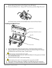
Installing the Media Assembly
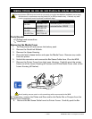
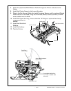
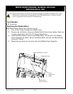
1. All Repair Kits: Assemble the Gap Sensor
Insert the sensor on the Gap Sensor Cable into the Plate, Edge Guide as shown.
The large hole in the cable will t over the mounting boss on the Plate, Edge
guide. Dress the grounding strap portion of the cable assembly away from the
Plate Edge Guide as shown.
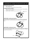
2. For RK16823-043 Only
Install the Gear, 32P, 14T on the Edge Guide Assembly. Squeeze the two media
Supports together as far as they will travel. Slide the Gear 32P, 14T over the
shaft on the Edge Guide Sub-Assembly, engaging the teeth on the two racks
with the teeth on the gear.
3. All Repair Kits: Install the Media Assembly
media guide aSSembLy, QL320/320 pLuS
You must use an ESD strap and work at a properly grounded workstation (antistatic mat or tray).
All electronic components must be placed on an ESD protective tray. If stored, any elec-
tronic components must be placed in antistatic bags.