


RMAN-QLS-002 rev. A Repair Procedures • 2-100 •
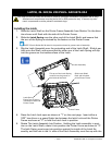
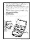
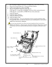
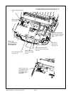
Printhead
Cable
LCD Cable
Label Presence Sensor Cable
Gap Sensor Cable
J4
J11
J1
J2
Keypad
Keypad
Motor Cable
Twist excess cable
Bar Sense Cable
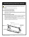
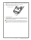
Notes:
For ease of assembly, install the Printhead and Motor Cables first, then install the optional
Media Width Cable.
Connectors for cables are polarized. The connectors will only fit in one direction. Do not
try to force the connectors in place.
Flex cables install in zero insertion force (ZIF) connectors. Pull the connector open, insert
the cable, and close the connector to retain the flex cable.
Dress all cables away from mounting bosses so they won’t get pinched during the next as-
sembly steps.
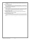
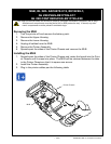
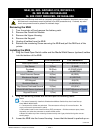
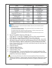
4. Set the Compatibility Switch per PCC digit 10:
If PCC digit 10 = 0, set SW1 to NORMAL CCW (turn fully counterclockwise ).
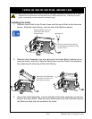
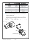
From # of connections MLB Connector #
Keypad Ground 1 (Flex) J1 (GROUND)-
Bar Sensor 3 (Flex) J2 (BAR)(bottom of board)-
Printhead 28 (Flex) J3 (PRINTHEAD)-
Motor 4 J4 (MOTOR)(bottom of board)-
Label Presence Sensor 4 (Flex) J5 (PEEL)-
Membrane Keypad 8 (Flex) J6 (KEYPAD)-
LCD Keypad 10 (Flex) J8 (LCD)-
QuickLink Module J9 (MODULE)-
Gap Sensor/Printhead Ground 5 (Flex) J10 (GAP)-
continued