


RMAN-QLS-002 rev. A Repair Procedures • 2-78 •
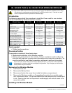
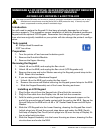
Tools needed
#1 Phillips Head Screwdriver.
3
/
32
” Hex Driver
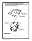
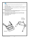
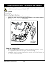
Removing the Printer Frame
1. Turn the printer off and remove the battery pack.
2. Remove the QuickLink Module.
3. Remove the Upper Housing.
4. Remove the MLB.
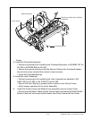
5. Remove the 4 Screws that secure the Printer Frame to the Lower Housing and
remove the Printer Frame.
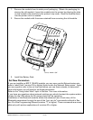
9. Remove the optional Media Width Sensor. If the Printer is equipped with the
Media Width Sensor option, pull the sensor cable free of the Printer Frame.
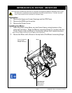
6. If necessary, remove and retain the following from the Printer Frame:
a. Media Cover.
b. Latch Assembly.
c. Media Assembly.
d. Printhead Assembly.
e. Motor.
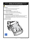
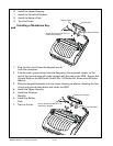
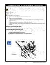
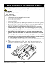
Install the new Printer Frame Assembly
1. Assemble the Media Assembly onto the new Printer Frame:
Refer to AN16753-001 for more details on installing the QL 420 Media Assembly.
• Ensure the Gap Sensor Cable is in place.
• Place the Media Assembly into the Printer Frame and rock it back into posi-
tion.
• Secure in place with (2) Screws.
• If equipped with the optional Media Width Sensor, dress the Sensor cable
through the retaining feature on the right hand side of the Printer Frame.
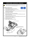
2. Assemble the Media Cover Assembly.
• Follow the procedure for reinstalling the Media Cover Assembly per AN16861-
024 for QL 320 and AN16753-025 for QL 420.
• Ensure the Hinge Pin passes behind the Sensor cable.
• Press the Sensor cable rmly into its channel in the bottom of the Printer
continued
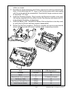
pRinteR fRame, QL 320/320 pLuS- an16861-029 &
QL 420/420 pLuS- an16753-012
You must use an ESD strap and work at a properly grounded workstation (antistatic mat or tray).
All electronic components must be placed on an ESD protective tray. If stored, any elec-
tronic components must be placed in antistatic bags.