


RMAN-QLS-002 rev. A Repair Procedures • 2-80 •
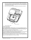
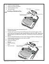
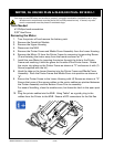
Cover.
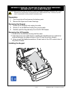
6. Re-attach the MLB and display.
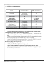
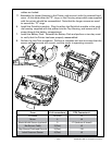
• Plug the cables from the printer back into the MLB per the following table:
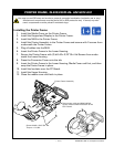
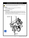
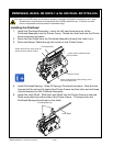
7. Reassemble the Upper Cover and Module Housing
• Re-install the Upper Housing per AN16861-010 (QL320) or AN16753-007 (QL
420).
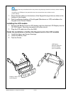
• When re-installing the Upper Housing for the QL 420, ensure that the proper
Corner Attachment Kit (ref. AN16753-010) is also re-installed.
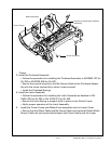
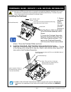
• Install the Module Housing as shown below Ensure the Module is secured
with the retained screw through the battery compartment.
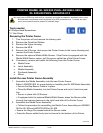
8. Install the Battery and test the unit.
• Install the Battery and turn the unit on.
• Verify that all indicator lights turn on properly.
• Verify proper operation of the printer by performing a two-key reset.
• It is recommended you perform a complete unit test to verify proper opera-
tion of all the printer features.
From # of connections CPU Connector #
Printhead Flex circuit J3
(28 conductor)
Motor Cable 4 J4
Media Width 3 J11 (bottom
Sensor (optional) of board)
Bar Sensor Cable Flex circuit J2
(3 conductor)
Gap Sensro/ Flex circuit J10
Printhead Ground (5 conductor)
Label Presence Sensor Flex Circuit J5
(4 conductor)