


RMAN-QLS-002 rev. A Repair Procedures • 2-84 •
You must use an ESD strap and work at a properly grounded workstation (antistatic mat or tray).
All electronic components must be placed on an ESD protective tray. If stored, any elec-
tronic components must be placed in antistatic bags.
Tools Needed
#1 Phillips head screwdriver
3/32” Hex Driver
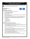
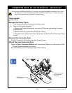
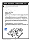
Removing the Motor
1. Turn the printer off and remove the battery pack
2. Remove the QuickLink Module
3. Remove the Upper Housing
4. Disconnect the MLB
5. Remove the Printer Frame and Media Cover Assembly from the Lower Housing.
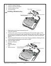
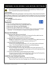
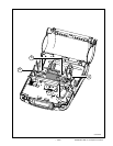
6. Remove the Motor (1) from the Printer Frame by removing its mounting Screw
(2) and twisting the motor away from the frame as shown at “2”.
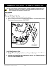
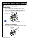
7. Install the new Motor by inserting the pinion through the hole in the Printer
Frame and meshing it with the gears on the side of the Printer frame. Rotate
the motor into place on the Printer Frame as shown at “3” and secure it with (1)
Screw (supplied with the kit) .
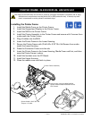
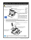
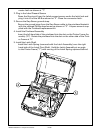
8. Hook the tabs on the Lower Housing into the Printer Frame and Media Cover
Assembly. Rock the Printer Frame and Media Cover into position as shown at
“4”.
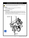
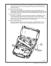
9. Secure the Printer Frame to the Lower Housing with (4) Screws as shown at “5”.
Ensure that none of the sensor cables or the motor cables are pinched between
the Printer Assembly and the Bottom Cover Prior to assembly.
For ease of handling, close the media cover, but leave the latch in the open posi-
tion.
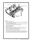
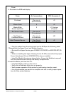
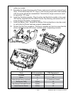
10. Plug the printer cables into the MLB. Using Table 1 as a guide, plug in the
cables from the Printer to the MLB. Ensure all ZIF connectors for the at ex
motoR, QL 320/320 pLuS & QL420/420 pLuS- RK18251-1
2
1
3