


• 2-103 • RMAN-QLS-002 rev. A Repair Procedures
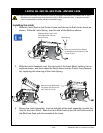
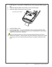
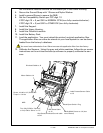
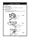
der the retainer features and sits on the locator pin in the Lower Housing.
4. Secure the Ground Strap with 1 Screw and Nylon Washer.
5. Install a second Screw to secure the MLB.
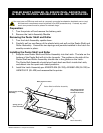
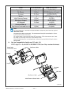
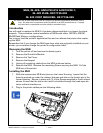
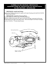
6. Set the Compatibility Switch per PCC digit 10
If PCC digit 10 = 0, set SW1 to NORMAL CCW (turn fully counterclockwise ).
If PCC digit 10 = S, set SW1 to OTHER CW (turn fully clockwise).
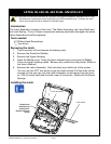
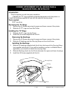
7. Install the Keypad.
8. Install the Upper Housing.
9. Install the QuickLink module.
10. Install the Battery Pack.
11. Load the application. You must reload the printer’s original application les.
The application les can either be stored on your local system or can be down-
loaded from the factory’s database.
You must have authorization from Zebra to access the application files from the factory.
12. Calibrate the Sensors. Using the gray and white swatches, follow the on-screen
instructions on the unit test and set-up software to properly calibrate the sen-
sors.
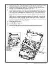
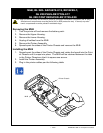
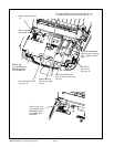
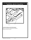
Media Width Sensor to J11 (bot-
tom of Board)
Head Open Switch- Plug
Bar Sense Cable
to J2
Gap Sense/Printhead Ground cable
to J10
MLB
Printhead Cable to J3
Screw, #4-40 x 1/4”, Socket Hd.
Torque = 5 in-lbs
Motor Cable to J4
Label Present Sensor Cable
to J5
Turn fully CCW for “Normal”
or fully CW to “Other” or “S”