


• 2-93 • RMAN-QLS-002 rev. A Repair Procedures
You must use an ESD strap and work at a properly grounded workstation (antistatic mat or tray).
All electronic components must be placed on an ESD protective tray. If stored, any elec-
tronic components must be placed in antistatic bags.
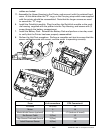
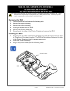
Latch, QL 220/QL 220 pLuS- an16972-004
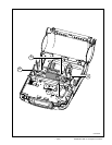
Installing the Latch
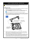
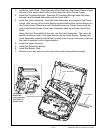
1. Slide the Latch Shaft on the Printer Frame Assembly from Station 3 in the direc-
tion shown until ush with the side of the Printer Frame.
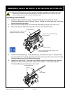
2. Slide the Latch Spring over the other end of the Latch Shaft, and ensure that
the arm of the Spring is retained by the feature on the Printer Frame.
NOTE: Flip the Peeler Bail forward in the position shown for greater ease of assembly.
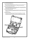
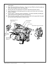
3. Slip the Latch Assembly over the protruding end of the Latch Shaft. Slide it par-
tially onto the Shaft and ensure that the other arm of the Latch Spring will slip
into the groove on the inside surface of the Latch.
Printer Frame
Latch Assembly
Slide Latch Shaft
ush with this side
of the Printer Frame
Latch Spring
Ensure arm of spring
is seated on feature of
Printer Frame.
This arm of the Latch Spring
must t into the groove on
the inside of the latch
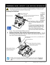
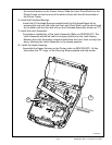
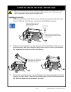
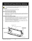
4. Press the Latch Lock open as shown at “1” on the next page. Insert either a
3/23” hex driver or a spare Peeler bar between the latch Lock and the Printer
Frame as shown at “2” to hold the Latch Lock in position.
5. Rotate The Latch Assembly Into Position. Holding the Latch assembly in posi-
tion on the Latch Shaft, rotate it into position the Printer Frame as shown at “3”.
The latch Spring must snap into position against the inside of the Latch As-
sembly, and the hole in the l.h. side of the Latch Assembly must line up with the