


RMAN-QLS-002 rev. A Repair Procedures • 2-52 •
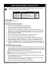
Kit p/n Description Type
RK18466-002 QL4 Linerless Belt
RK18466-003 QL4 w/ Media Width Belt
RK18466-004 QL4 Linerless w/Media Width Belt
AN16753-001 QL4 Media Assy Gear
Tools needed
#1 Phillips Head Screwdriver.
3
/
32
” hex driver
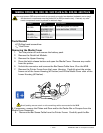
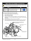
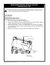
Removing the Media Assembly
1. Turn the printer off and remove the battery pack.
2. Remove the QuickLink Module and retain the parts.
3. Remove the Upper Housing and retain the parts.
4. Unplug the following cables from the MLB: J5 (Label Presence Sensor), J10
(Gap Sensor). If unit has the Media Width Sensor option, unplug J11 from the
bottom of the board. Unplug the Printhead, Motor, Head-up switch, and Bar
sense cables from the MLB.
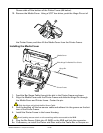
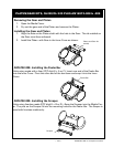
5. Remove the Printer Frame and Media Cover and retain the parts.
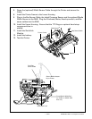
7. Remove the Gap Sensor Cable Ground from the Printhead.
8. Remove and retain the Screws securing the Media Assembly to the Printer.
9. Remove the optional Media Width Sensor. If the Printer is equipped with the
Media Width Sensor option, pull the sensor cable free of the Printer Frame.
10. Remove the Media Assembly. Rock the Media Assembly forward and then lift
it away from the Printer Frame. Keep the Gap Sensor Cable with the Media As-
sembly.
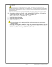
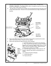
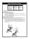
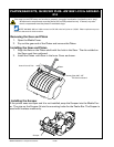
Installing the Media Assembly
1. Install the Media Assembly: Slip the Media Assembly into the slot in the Printer
Frame. Note that the tab on the bottom of the Media Assembly ts into the slot
on the bottom of the printer frame. On -003 and -004 kits only: Dress the Media
Width Sensor Assembly through the Printer Frame
Note: Pull the Rack Lock to the left as shown in this view while assembling to allow the Me-
dia Assembly to sit in the printer frame. Dress the (optional) Media Width Sensor Assembly
through the slot in the side of the Printer Frame
2. Dress the Gap Sensor Cable. Fold the Gap Sensor Cable and dress it through
the slot on the printer frame.
3. Secure the Media Assembly to the Printer Frame with screws from the motor
side of the Printer Frame. Do not pinch any cables.
5. Secure the Gap Sensor Cable Ground to the Printhead.
media guide aSSembLy, QL420/420 pLuS
You must use an ESD strap and work at a properly grounded workstation (antistatic mat or tray).
All electronic components must be placed on an ESD protective tray. If stored, any elec-
tronic components must be placed in antistatic bags.