


• 2-51 • RMAN-QLS-002 rev. A Repair Procedures
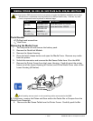
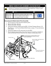
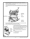
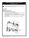
Slip the Media Assembly into the slot in the Printer Frame. RK16823-043,
RK18462-1, RK18463-1: The Media Width cable is dressed through two slots and
a tab in the Printer Frame as shown.
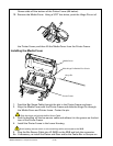
4. The Gap Sensor Cable must be folded over and dressed through the slot on the
printer frame as shown. Ensure it is not pinched before securing the Media As-
sembly.
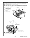
5. Secure the Media Assembly to the Printer Frame with screws from the motor
side of the Printer Frame. Do not pinch any cables.
6. Secure the Gap Sensor Cable Ground to the Printhead.
7. Install the Printer Frame to the Lower Housing.
8. Plug in the Bar Sensor Cable, the Label Presence
Sensor and the optional Media Width Sensor to the
MLB. Plug the Printhead, Motor, Head-up switch,
and Bar sense cables into the MLB.
9. Install the Upper Housing. Ensure that the “D”-
Rings or optional hand strap components are in-
stalled.
10. Install the QuickLink Module.
11. Install the battery.
12. Test the Printer.
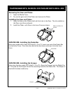
Dress the
Sensor cable
through here.
Dress Media
Width Sensor
Cable through
Printer Frame
Ensure Media
Sensor cable is
behind holding
feature.
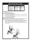
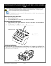
Bottom
edge of
Edge Guide
Assem-
bly fits
between
these rails.
Screw, 4-40 x 1/4”
Socket Hd. (2 p/u)