


RMAN-QLS-002 rev. A Repair Procedures • 2-86 •
Installing the Printhead
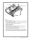
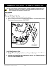
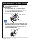
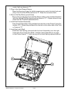
1. Install the Printhead Assembly. Insert the left hand mounting ear of the
Printhead Assembly into the Printer Frame. Rotate the other end into the Printer
frame and snap into place.
2. Dress the Flex Cable from the Printhead Assembly through the Latch Lock.
3. Dress the Sensor Cable through the cutout on the Printer Frame.
Printhead Assy.
Insert this end rst, then pivot op-
posite end into Printer Frame.
Insert sensor cable through
this coutout
Printer Frame
Insert printhead ex cable through cout-
out in the Latch lock.
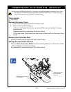
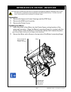
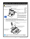
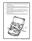
4. Install Printhead Springs. Snap (2) Springs, Printhead into place. Note that the
loop end of the springs t against the Printer Frame, and the other end will snap
into slot features on the Printhead Assembly.
5. Install the Latch Shaft. Slide the Latch Shaft into the Printer Frame so that the
Shaft protrudes from either side of the Printer Frame. The loops from the
Printhead Springs should rest on the shaft.
Printhead Springs
Latch Shaft
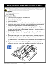
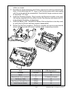
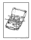
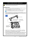
pRinthead, QL220- RK18278-1 & QL 220 pLuS- RK17735-016
You must use an ESD strap and work at a properly grounded workstation (antistatic mat or tray).
All electronic components must be placed on an ESD protective tray. If stored, any elec-
tronic components must be placed in antistatic bags.