


AT-WA7500 and AT-WA7501 Installation and User’s Guide
19
Understanding
the Ports
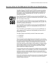
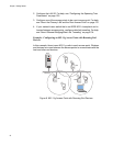
The access point may have up to four ports.
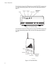
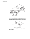
To access the ports on the AT-WA7501, you must remove the cable
access door.
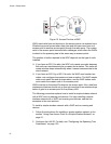
To remove the AT-WA7501 cable access door
1. Unscrew the two thumbscrews on the cable access door.
2. Remove the door.
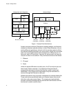
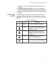
This illustration shows the ports that are on the AT-WA7501. For help
understanding these ports, see the Port Descriptions table on page 19.
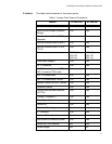
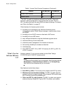
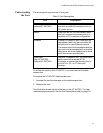
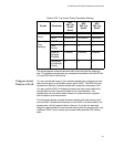
Table 3. Port Descriptions
Port Description
Power (Not AT-WA7500,
optional AT-WA7501)
Used with an appropriate power cable,
this port connects the access point to an
AC power source.
Serial Used with an RS-232 null-modem cable,
this port connects the access point to a
terminal or PC to perform configuration.
Ethernet 10BaseT/100BaseTx port. Used with an
appropriate cable, this port connects the
access point to your Ethernet network.
The access point auto-negotiates with the
device it is communicating with so that the
data rate is set at the highest rate at which
both devices can communicate.
Fiber optic
(Not AT-WA7500,
optional AT-WA7501)
Optional 100BaseFX port. You must use a
patch cable with a female MT-RJ
connector to connect the access point to
your MT-RJ, SC, or ST fiber optic
network.