Modbus Communications - Implementation Basics
5Liebert
®
IntelliSlot
®
Modbus/BACnet IP
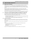
2.0 MODBUS COMMUNICATIONS
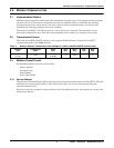
2.1 Implementation Basics
Modbus protocol provides control and data acquisition, through query and response, between master
and slave devices. This protocol comprises the rules for communication, controlling the message
format between devices, how master and slave devices initiate communications, as well as unit
identification, message-handling and error-checking.
The Liebert IntelliSlot
®
485/IP card acts as a slave device on a network. This network can be a
multidrop configuration over EIA-485, where multiple slaves reside on a common wire or loop.
2.2 Transmission Format
The Liebert IntelliSlot 485/IP interface card supports Modbus Remote Terminal Unit (RTU)
transmission modes. See Table 2 below.
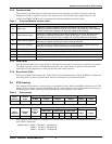
2.3 Modbus Packet Format
Each Modbus packet consists of these fields:
• Device Address
• Function Code
• Data Field(s)
• Error Check Field
2.3.1 Device Address
The address field immediately follows the beginning of the frame and consists of 8-bits (RTU). This bit
indicates the user-assigned address of the slave device that is to receive the message from the
attached master device.
Each slave must be assigned a unique address. Only the addressed slave will respond to a query that
contains its address.
Table 2 Modbus Remote Transmission Unit settings for Liebert IntelliSlot 485/IP interface card
Physical
Port
Transmission
Mode
Baud
Rate
Data
Bits
Parity
Bits
Stop
Bits
Start
Bits
EIA-485/422
2 wire
RTU
9600, 19200
or 38400
8None1 1


