


Modbus 485 and Modbus IP Protocols - Thermal Management Products
Liebert
®
IntelliSlot
®
Modbus/BACnet IP 82
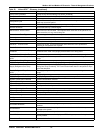
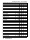
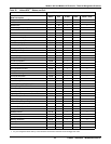
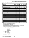
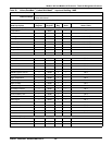
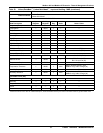
Table 26 Liebert XDF
™
- Input and Holding
Controller Liebert iCOM
®
v3
Data Description
Input
Register
Holding
Register
# of
Reg. Scale Notes / Units
Vendor ID 30001 40001 1 — —
Device ID 30002 40002 1 — —
Version number 30003 40003 1 — —
UPS/Env/Pwr 30004 40004 1 — —
Temperature Setpoint 30023 40023 1 10 deg C
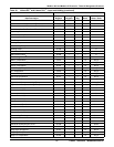
Delay after safe Temp has been reached 30034 40034 — — Minutes
Allowable deviation between internal temp sensors 30035 40035 — — deg C
High Cabinet Temperature Setpoint 30058 40058 — 10 deg C
Low Cabinet Temperature Setpoint 30059 40059 — 10 deg C
Fan Run Hour Threshold 30070 40070 — — Hours
Compressor 1 Run Hour Threshold 30071 40071 — — Hours
Service Ramp 30099 — — — %
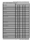
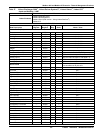
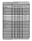
Operating State
6
30100 — — — —
Number of Active Events/Alarm 30101 — — — —
Summary Alarm Status
7
30102 — — — —
Fan Ramp 30103 — — — %
Cooling Ramp 30104 — — — %
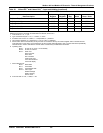
Digital Scroll Compressor 1 High Temperature 30119 — — 10 deg C
Sensor 1 Temp 30121 — — 10 deg C
Sensor 2 Temp 30122 — — 10 deg C
Sensor 3 Temp 30123 — — 10 deg C
Sensor 4 Temp 30124 — — 10 deg C
Ambient Temp 30125 — — 10 deg C
Ambient Humidity 30126 — — — %
Dew Point Temp 30127 — — — deg C
Adjusted Setpoint Temp 30128 — — 10 deg C
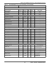
Cabinet Temperature 30129 — — 10 deg C
Service Due Year 30135 — — — —
Service Due Month 30136 — — — —
Device kW Load 30137 — — — kW
Fan Run Hour 30141 — — — Hours
Compressor 1 Run Hour 30142 — — — Hours
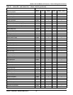
NOTES
If the Scale column has a value for a Data Description, divide the Modbus value by the value in the Scale column to get the scaled value.
Reference Document: ST100I&C PA Parameters and Events, Version 18.0
1. Timer mode: 0 = no, 1 = yes
2. Type of DT Room-Glycol: 0 = no, 1 = contact, 2 = value
3. Predictive Hum Control: 0 = relative, 1 = compensated, 2 = predictive
4. Temp Control Algorithm: 0 = proportional, 1 = PD, 2 = PDI; 3 = intelligent
5. When VFD is set to manual mode (coil 22), the host can control the VFD by the value of register 40019. The Manual VSD
Timer will start to count down. Once it reaches 0, the VFD control mode will switch to auto. The host will need to periodically
reset this timer in order to maintain the manual mode. Consult factory for BMS timer information.
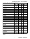
6. Operating state:
Bit 0-1: 00 unit off, 01 unit on, 10 unit standby
Bit 2-3: 00 auto, 01 manual
Bit 4-7: 0000 none
0001 local user
0010 alarm
0011 schedule
0100 remote user
0101 external device
0110 local display
7. Alarm state bit map:
Bit 0 = Reset state
Bit 1 = Active state
Bit 2 = Acknowledge state
Bit 3-7 = Alarm Type
00000: Message
00001: Warning
00010: Alarm
8. Free-cool state: 0 = Off, 1 = Start, 2 = On