BACnet Communications - UPS Systems
Liebert
®
IntelliSlot
®
Modbus/BACnet IP 304
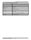
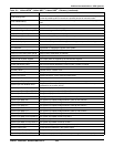
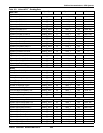
Load Sharing Fault
Difference between any phase inverter current of unit and the relevant average output
current of parallel system is more than a specific percent of nominal current.
Loss of Redundancy
The multi-module collection doesn't have enough modules to redundantly support the
load
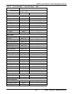
Main Battery Disconnect Open Main battery disconnect is open
Mains Input Neutral Lost Loss of neutral in the input source is detected.
Maintenance Bypass Breaker (MBB) Maintenance bypass breaker (MBB)
MMS On Battery The multi-module system is on battery
MMS Output Apparent Power The sum total apparent power of all system output modules
MMS Output Power The sum total power of all system output modules
MMS Over Capacity The multi-module system load is larger than the apparent power limit setting.
MMS Overload Multi-module system overload
On Generator A generator is supplying the power to the system
Output Current Crest Factor Phs A Output current crest factor of Phase A.
Output Current Crest Factor Phs B Output current crest factor of Phase B.
Output Current Crest Factor Phs C Output current crest factor of Phase C.
Output Load on Maint. Bypass The output power is supplied by the maintenance bypass
Parallel Comm Warning Parallel communication bus warning
Power Sub Module Fault One or more failures detected in power module, inverter or rectifier.
Power Supply Failure Power supply failure
Rectifier Failure Rectifier failure - rectifier is off
System Date and Time The system date and time
System Fan Failure System fan failure - one or more fans have failed
System Input Current Imbalance System Input Currents are Imbalanced
System Input Frequency The system input frequency
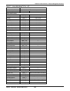
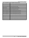
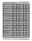
System Input Phs Rotation Error
The power conductors on the input line are not wired to the UPS in the sequence
preferred for the rectifier (A-B-C)
System Input Power Factor Phs A The system input power factor for Phase A
System Input Power Factor Phs B The system input power factor for Phase B
System Input Power Factor Phs C The system input power factor for Phase C
System Input Power Problem The input is not qualified to provide power to the system
System Input RMS A-B The System Input RMS Voltage between Phase A and Phase B
System Input RMS A-N The System Input RMS Voltage between Phase A and Neutral
System Input RMS B-C The System Input RMS Voltage between Phase B and Phase C
System Input RMS B-N The System Input RMS Voltage between Phase B and Neutral
System Input RMS C-A The System Input RMS Voltage between Phase C and Phase A
System Input RMS C-N The System Input RMS Voltage between Phase C and Neutral
System Input RMS Current Phase A The system input RMS current for Phase A
System Input RMS Current Phase B The system input RMS current for Phase B
System Input RMS Current Phase C The system input RMS current for Phase C
System Output Apparent Power The sum total apparent power of all system output phases
System Output Fault A fault has been detected in the system output
System Output Frequency The system output frequency
System Output Pct Power Phase A The system output power on phase A as a percentage of the rated capacity
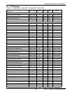
Table 101 Liebert APM
™
, Liebert NXC
™
, Liebert NXR
™
- Glossary (continued)
Data Label Data Description


