


BACnet Communications - UPS Systems
Liebert
®
IntelliSlot
®
Modbus/BACnet IP 356
Battery Volts at Main Disconnect
The voltage between the positive and the negative battery terminals of the
common battery disconnect
Battery Volts for Cabinet
The voltage between the positive and negative battery terminals of a battery
cabinet
Bypass - Manual Rexfr Inhibited Manual transfer from bypass to inverter is inhibited.
Bypass - Manual Xfr Inhibited Manual transfer from inverter to bypass is inhibited.
Bypass Auto Retransfer Failed
After performing a recoverable transfer to bypass, an attempt to auto retransfer
from bypass to inverter failed
Bypass Auto Transfer Failed An automatic transfer to static bypass failed
Bypass Frequency Error The bypass frequency is outside the inverter synchronization limits
Bypass Input Frequency The bypass input frequency
Bypass Input Voltage RMS A-B The bypass input RMS voltage between phases A and B
Bypass Input Voltage RMS B-C The bypass input RMS voltage between phases B and C
Bypass Input Voltage RMS C-A The bypass input RMS voltage between phases C and A
Bypass Input Wire Configuration Bypass input wire configuration
Bypass Isolation Breaker for Module 1 Bypass isolation breaker for module 1
Bypass Isolation Breaker for Module 2 Bypass isolation breaker for module 2
Bypass Isolation Breaker for Module 3 Bypass isolation breaker for module 3
Bypass Isolation Breaker for Module 4 Bypass isolation breaker for module 4
Bypass Isolation Breaker for Module 5 Bypass isolation breaker for module 5
Bypass Isolation Breaker for Module 6 Bypass isolation breaker for module 6
Bypass Isolation Breaker for Module 7 Bypass isolation breaker for module 7
Bypass Isolation Breaker for Module 8 Bypass isolation breaker for module 8
Bypass Isolation Breaker Bypass isolation breaker
Bypass Nominal Voltage Bypass nominal (or rated) voltage
Bypass Not Available A problem associated with the bypass has been detected
Bypass Overload Phase A An overload exists on output phase A while operating on the bypass
Bypass Overload Phase B An overload exists on output phase B while operating on the bypass
Bypass Overload Phase C An overload exists on output phase C while operating on the bypass
Bypass Qualification Status bypass qualification status
Bypass SS Overload Time Remain
The calculated time remaining before bypass static switch shutdown due to the
present overload condition
Bypass Static Switch Overload Bypass off due to static switch overload
Bypass Static Switch Unavailable The static bypass switch is off, and unable to operate
Bypass Sync Phase Difference The phase angle difference between the inverter output and bypass source
Configuration Description Configuration description
Continuous Operation - ECO Mode
This setting gives the user the ability to Enable/Disable ECO Mode continuous
operation.
Controls Reset Required A controls reset is required due to one or more critical settings changing
DC Bus Current
The current at the battery input terminals. In charging mode, the current will be a
positive value. In discharging mode, the current will be a negative value
DC Bus Low Fault The DC Bus voltage has reached a critical low level.
DC Bus Qualification Status dc bus qualification status
DC Bus Voltage
The voltage between the positive and negative terminals of the DC bus at the
battery input
ECO Mode Active Conditions for Activation or Automatic Reactivation have been satisfied.
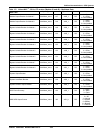
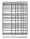
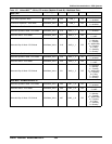
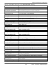
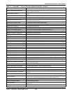
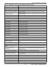
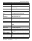
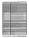
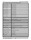
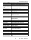
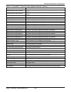
Table 113 Liebert NXL
™
- 50 Hz, CE version (Models 48 and 49)—Glossary
Data Label Data Description