


Configuring IP
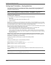
USING THE WEB MANAGEMENT INTERFACE
1. Log on to the device using a valid user name and password for read-only or read-write access. The System
configuration panel is displayed.
2. Click on the plus sign next to Command in the tree view to list the command options.
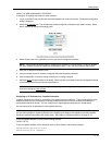
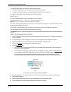
3. Select the Trace Route
link to display the Trace Route panel.
4. Enter the host name or IP address in the Target Address field.
NOTE: You can use the host name only if you have already configured the DNS resolver for the domain that
contains the host.
5. Optionally change the minimum and maximum TTLs and the Timeout.
6. Click on Start to begin the trace. The trace results are displayed below the Start and Abort buttons.
Configuring Packet Parameters
You can configure the following packet parameters on routing switches. These parameters control how the routing
switch sends IP packets to other devices on an Ethernet network. The routing switch always places IP packets
into Ethernet packets to forward them on an Ethernet port.
• Encapsulation type – The format for the Layer 2 packets within which the routing switch sends IP packets.
• Maximum Transmission Unit (MTU) – The maximum length of IP packet that a Layer 2 packet can contain. IP
packets that are longer than the MTU are fragmented and sent in multiple Layer 2 packets.
Changing the Encapsulation Type
The routing switch encapsulates IP packets into Layer 2 packets, to send the IP packets on the network. (A Layer
2 packet is also called a MAC layer packet or an Ethernet frame.) The source address of a Layer 2 packet is the
MAC address of the routing switch interface sending the packet. The destination address can be one of the
following:
• The MAC address of the IP packet’s destination. In this case, the destination device is directly connected to
the routing switch.
• The MAC address of the next-hop gateway toward the packet’s destination.
• An Ethernet broadcast address.
The entire IP packet, including the source and destination address and other control information and the data, is
placed in the data portion of the Layer 2 packet. Typically, an Ethernet network uses one of two different formats
of Layer 2 packet:
• Ethernet II
• Ethernet SNAP (also called IEEE 802.3)
The control portions of these packets differ slightly. All IP devices on an Ethernet network must use the same
format. HP routing switches use Ethernet II by default. You can change the IP encapsulation to Ethernet SNAP
on individual ports if needed.
NOTE: All devices connected to the routing switch port must use the same encapsulation type.
To change the encapsulation type on a routing switch port, use either of the following methods.
USING THE CLI
To change the encapsulation type on interface 1/5 to Ethernet SNAP, enter the following commands:
HP9300(config)# int e 1/5
HP9300(config-if-5)# ip encapsulation ethernet_snap
Syntax: ip encapsulation ethernet_snap | ethernet_ii
6 - 23