


Advanced Configuration and Management Guide
Configuration Examples
This section shows two complete configuration examples for NAT. The examples are based on different network
topologies.
• NAT clients connected to the routing switch by a switch.
• NAT clients connected directly to routing switch ports.
NOTE: You also can enable the feature on the primary port of a trunk group, in which case the feature applies to
all the ports in the trunk group. These examples do not show this configuration.
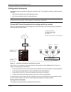
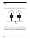
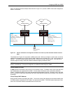
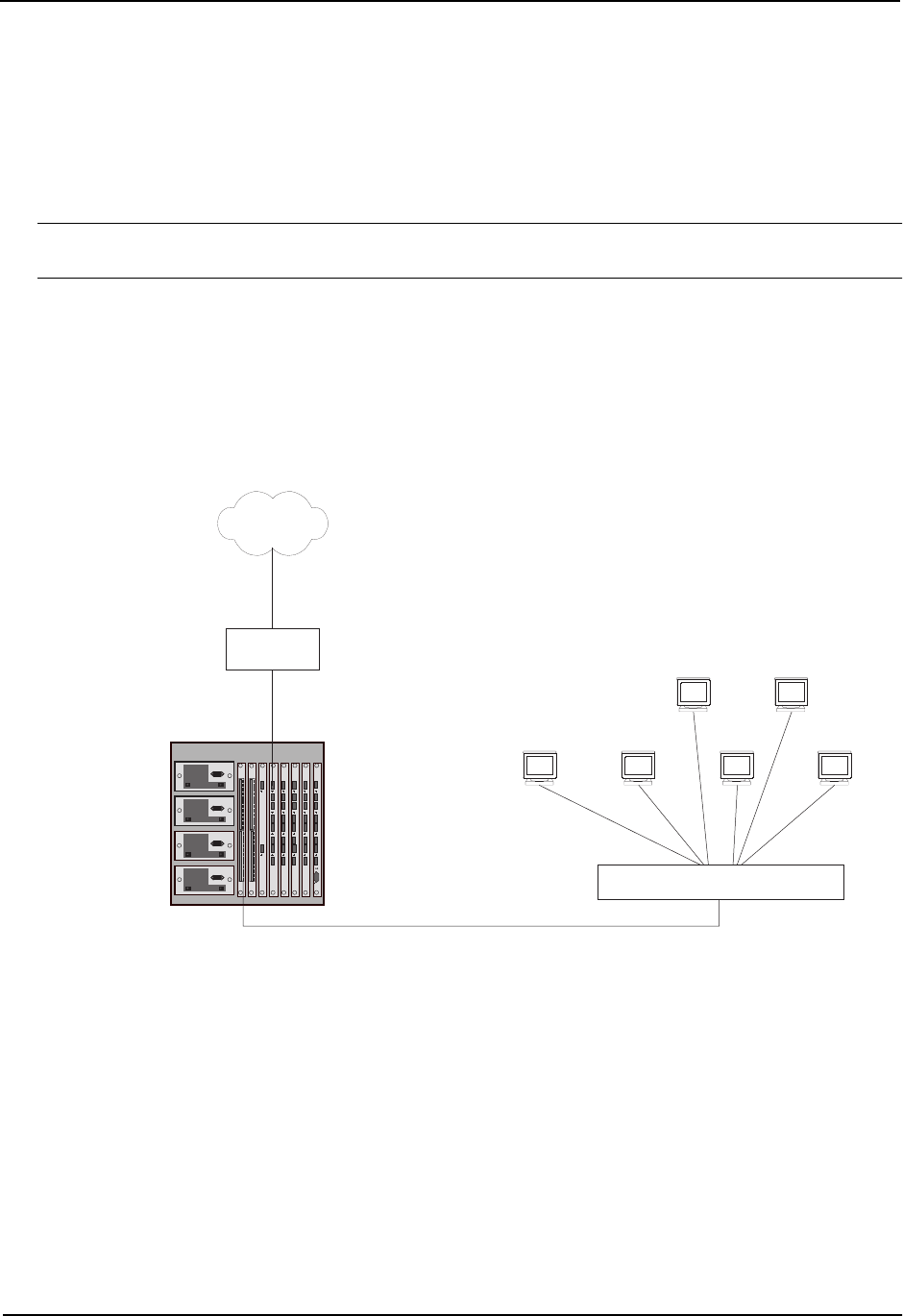
Private NAT Clients Connected to the routing switch by a switch
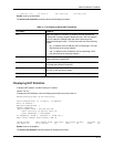
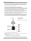
Figure 11.2 shows an example of a NAT configuration in which the clients in the private network are attached to
the routing switch through a switch.
Outside NAT interface
Port 4/1
63.251.295.46/26
Inside NAT interface
Port 1/24
10.10.10.50/26
The device performs NAT
for traffic between the outside
NAT interface and the inside
NAT interface.
Internet
10.10.10.7
NAT Pool = 63.251.295.47/26 - 63.251.295.48/26
Internet
access router
10.10.10.6
10.10.10.5
10.10.10.4 10.10.10.3
10.10.10.2
10.10.10.49/26
63.251.295.1/26
HP Switch 4000
Figure 11.2 NAT clients connected the routing switch by a switch
Here are the CLI commands for implementing the NAT configuration for the HP 9308M shown in Figure 11.3.
These commands configure the following:
• An Access Control List (ACL) for the range of private addresses in the private network on virtual interface 10
• A Pool of public (Internet) address to use for translation of the private addresses
• An association of the ACL for the private addresses with the pool for translation
• A default route that has the Internet access router as the route’s next-hop gateway
The commands also enable inside NAT and outside NAT on the ports connected to the private network’s switch
and to the Internet access router, and save the configuration changes to the startup-config file.
Routing Switch Commands
The following commands access the configuration level of the CLI.
11 - 14