


Configuring RIP
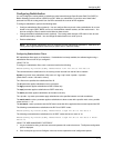
5. Enter the filter ID.
6. Select either Permit or Deny as the action.
7. Enter an IP address and mask or the wildcard value, 0.0.0.0, to allow all routes.
8. Click the Add button to save the change to the device’s running-config file.
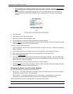
9. Select the Save
link at the bottom of the dialog. Select Yes when prompted to save the configuration change
to the startup-config file on the device’s flash memory.
To modify or delete a RIP route filter:
1. Log on to the device using a valid user name and password for read-write access. The System configuration
panel is displayed.
2. Click on the plus sign next to Configure in the tree view to expand the list of configuration options.
3. Click on the plus sign next to RIP in the tree view to expand the list of RIP option links.
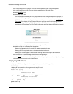
4. Select the Route Filter
link.
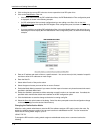
5. Click on the Modify button or Delete button to the right of the row describing the filter.
6. If you are modifying a filter, see the procedure above for configuration information.
7. Select the Save
link at the bottom of the dialog. Select Yes when prompted to save the configuration change
to the startup-config file on the device’s flash memory.
Applying a RIP Route Filter to an Interface
Once you define RIP route filters, you must assign them to individual interfaces. The filters do not take effect until
you apply them to interfaces. When you apply a RIP route filter, you also specify whether the filter applies to
learned routes or advertised routes:
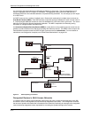
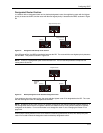
• Out filters apply to routes the routing switch advertises to its neighbor on the interface.
• In filters apply to routes the routing switch learns from its neighbor on the interface.
USING THE CLI
To apply RIP route filters to an interface, enter commands such as the following:
HP9300(config)# interface ethernet 1/2
HP9300(config-if-1/2)# ip rip filter-group in 2 3 4
Syntax: [no] ip rip filter-group in | out <filter-list>
These commands apply RIP route filters 2, 3, and 4 to all routes learned from the RIP neighbor on port 1/2.
USING THE WEB MANAGEMENT INTERFACE
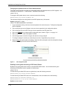
1. Log on to the device using a valid user name and password for read-write access. The System configuration
panel is displayed.
7 - 15