


Advanced Configuration and Management Guide
Configuring DVMRP
Enabling DVMRP on the Routing Switch and Interface
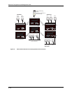
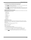
Suppose you want to initiate the use of desktop video for fellow users on a sprawling campus network. All
destination workstations have the appropriate hardware and software but the routing switches that connect the
various buildings need to be configured to support DVMRP multicasts from the designated video conference
server as seen in Figure 9.5.
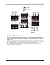
DVMRP is enabled on each of the HP routing switches shown in Figure 9.5, on which multicasts are expected.
You can enable DVMRP on each routing switch independently or remotely from one HP 9308M by a Telnet
connection. Follow the same steps for each routing switch. A reset of the routing switch is required when DVMRP
is first enabled. Thereafter, all changes are dynamic.
NOTE: By default, the DVMRP feature is disabled. To enable DVMRP on router1, enable DVMRP at the global
level and then on each interface that will support the protocol.
USING THE CLI
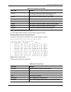
To enable DVMRP on Router 1 and interface 3, enter the following:
Router1(config)# router dvmrp
Router1(config-dvmrp-router)# int e 3
Router1(config-if-3)# ip dvmrp
USING THE WEB MANAGEMENT INTERFACE
To enable DVMRP on Router 1 and interface 3, enter the following:
1. Log on to the device using a valid user name and password for read-write access.
2. If you have not already enabled DVMRP, enable it by clicking on the Enable radio button next to DVMRP on
the System configuration panel, then clicking Apply to apply the change.
3. Click on the plus sign next to Configure in the tree view to expand the list of configuration options.
4. Click on the plus sign next to DVMRP in the tree view to expand the list of DVMRP option links.
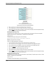
5. Click on the Virtual Interface
link to display the DVMRP Interface configuration panel.
NOTE: If the device already has DVMRP interfaces, a table listing the interfaces is displayed. Click the
Modify button to the right of the row describing an interface to change its configuration, or click the Add Virtual
Interface link to display the DVMRP Interface configuration panel.
6. Select the interface type. You can select Subnet or Tunnel.
7. Select the IP address of the interface being configured from the Local Address pulldown menu.
8. If you are configuring an IP Tunnel, enter the IP address of the destination interface, the end point of the IP
Tunnel, in the Remote Address field. IP tunneling must also be enabled and defined on the destination router
interface as well.
NOTE: The Remote Address field applies only to tunnel interfaces, not to sub-net interfaces.
9. Modify the time to live threshold (TTL) if necessary. The TTL defines the minimum value required in a packet
in order for the packet to be forwarded out the interface.
NOTE: For example, if the TTL for an interface is set at 10, it means that only those packets with a TTL
value of 10 or more will be forwarded. Likewise, if an interface is configured with a TTL Threshold value of 1,
all packets received on that interface will be forwarded. Possible values are 1 – 64. The default value is 1.
10. Click Enable or Disable next to Advertise Local to enable or disable the feature.
9 - 42