


Advanced Configuration and Management Guide
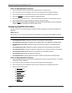
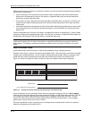
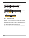
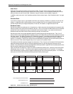
Untagged Packet Format
6 bytes
Destination
Address
6 bytes
Source
Address
2 bytes
Type
Field
Up to 1500 bytes
Data
Field
4 bytes
CRC
Ethernet II
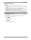
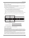
802.1q Tagged Packet Format
IEEE 802.3
Ethernet II with 802.1q tag
IEEE 802.3 with 802.1q tag
6 bytes
Destination
Address
6 bytes
Source
Address
2 bytes
Length
Field
Up to 1496 bytes
Data
Field
4 bytes
CRC
6 bytes
Destination
Address
6 bytes
Source
Address
4 bytes
802.1q
Tag
2 bytes
Type
Field
Up to 1500 bytes
Data
Field
4 bytes
CRC
6 bytes
Destination
Address
6 bytes
Source
Address
4 bytes
802.1q
Tag
2 bytes
Length
Field
Up to 1496 bytes
Data
Field
4 bytes
CRC
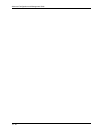
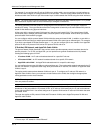
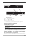
Octet 1
Tag Protocol Id (TPID)
Octet 2
1
802.1p
(3 bits)
2 3 4 5 6
VLAN ID (12 bits)
7 8 Octet 4
Figure 16.4 Packet containing the 802.1Q VLAN tag
NOTE: You cannot configure a port to be a member of the default port-based VLAN and another port-based VLAN
at the same time. Once you add a port to a port-based VLAN, the port is no longer a member of the default VLAN.
The port returns to the default VLAN only if you delete the other VLAN(s) that contains the port.
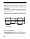
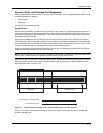
If you configure a VLAN that spans multiple devices, you need to use tagging only if a port connecting one of the
devices to the other is a member of more than one port-based VLAN. If a port connecting one device to the other
is member of only a single port-based VLAN, tagging is not required.
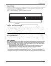
If you use tagging on multiple devices, each device must be configured for tagging and must use the same tag
value. In addition, the implementation of tagging must be compatible on the devices.
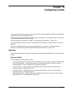
Figure 16.5 shows an example of two devices that have the same Layer 2 port-based VLANs configured across
them. Notice that only one of the VLANs requires tagging.
16 - 6